Introduction
The human low lumbar spine and pelvis compromise a
complex system that is required for the maintenance of balance. For
sagittal balance, several parameters, including pelvic incidence
(PI), pelvic tilt (PT) and sacral slope (SS) (1–3) have
been defined to evaluate the alignment of the spino-pelvic complex.
These parameters cooperate to regulate sagittal balance between the
spine and pelvis in order to keep an individual standing in an
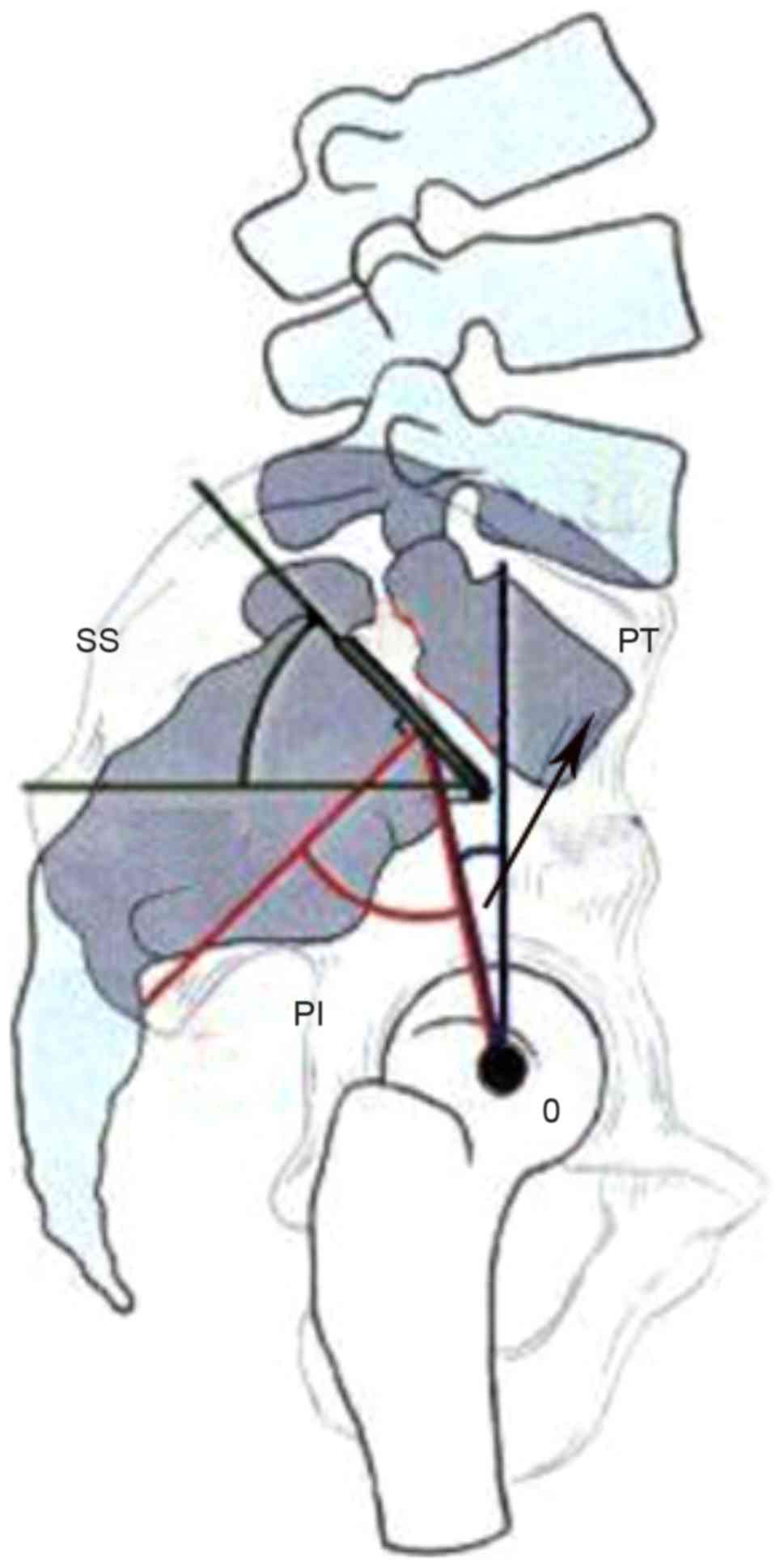
erect position (4). PI is the angle
created by the intersection of a line drawn from the center of the
femoral heads to the middle of the sacral plate and a line running
perpendicular to the middle of the sacral plate, and PT is the
angle between the vertical and a line drawn from the center of the
femoral heads to the center of the upper sacral endplate. PI is a
morphological constant for an individual in adulthood (4). However, the SS, which is defined as the
angle between the superior plate of S1 and a horizontal line as
shown in Fig. 1, is a parameter
changing with age (4). The geometric
relation between PI, PT and SS is as follows: PI=PT + SS. When the
lumbar spine endures intervertebral disc degeneration or certain
other spinal diseases, it may lose lordosis; however, the
spine-pelvis complex has the capability to compensate for sagittal
imbalance of the spine through pelvic retroversion with changing SS
(4). The change of SS secondary to
reduction of lumbar lordosis affects the biomechanics of the lumbar
spine and results in a deterioration of sagittal balance.
The biomechanical response of the human lumbar spine
has been investigated via experimental or computational approaches
for decades. However, SS may be an ignored or rejected factor in
these two approaches for various reasons. Above all, it is
difficult to determine the SS parameter from experimentation using
cadaver samples. Therefore, the data obtained from in vitro
experiments is not able to clearly indicate the variation in
biomechanical behavior that results from a changing SS (5–10). In
computational analysis using a finite element method (FEM),
magnitudes and distributions of displacements, stresses and range
of motion (ROM) under different daily physical motions can be
provided. However, few studies (11–15) have
considered the effect of a changing SS caused by structural
compensation. Furthermore, if the influence of SS on ROMs, stress
and strain distribution of the spine is known, this may be
beneficial in the preparation of personalized fusion implant
designs and therapeutic schedules. Hence, for focusing on
investigating the biomechanical behaviors of the low lumbar spine
segment with a changing SS caused by structural compensation, a
computational model with the capability for parametric study is
required so that complex in vivo and in vitro
experiments are not necessary. In the present study, a
three-dimensional finite element (FE) model including the L4-S1
segment was developed, then modified with different SS. Following
model validation, four daily physical motions including flexion,
extension, lateral bending and torsion were simulated to predict
the alteration of biomechanical responses under a changing SS.
Materials and methods
Lumbar finite element model
(L4-S1)
In an FEM, a geometrical complex spine segment can
be divided into different regions according to its anatomical
structure, and then meshed with various types of elements. Each
region can be assigned an appropriate material model to reflect its
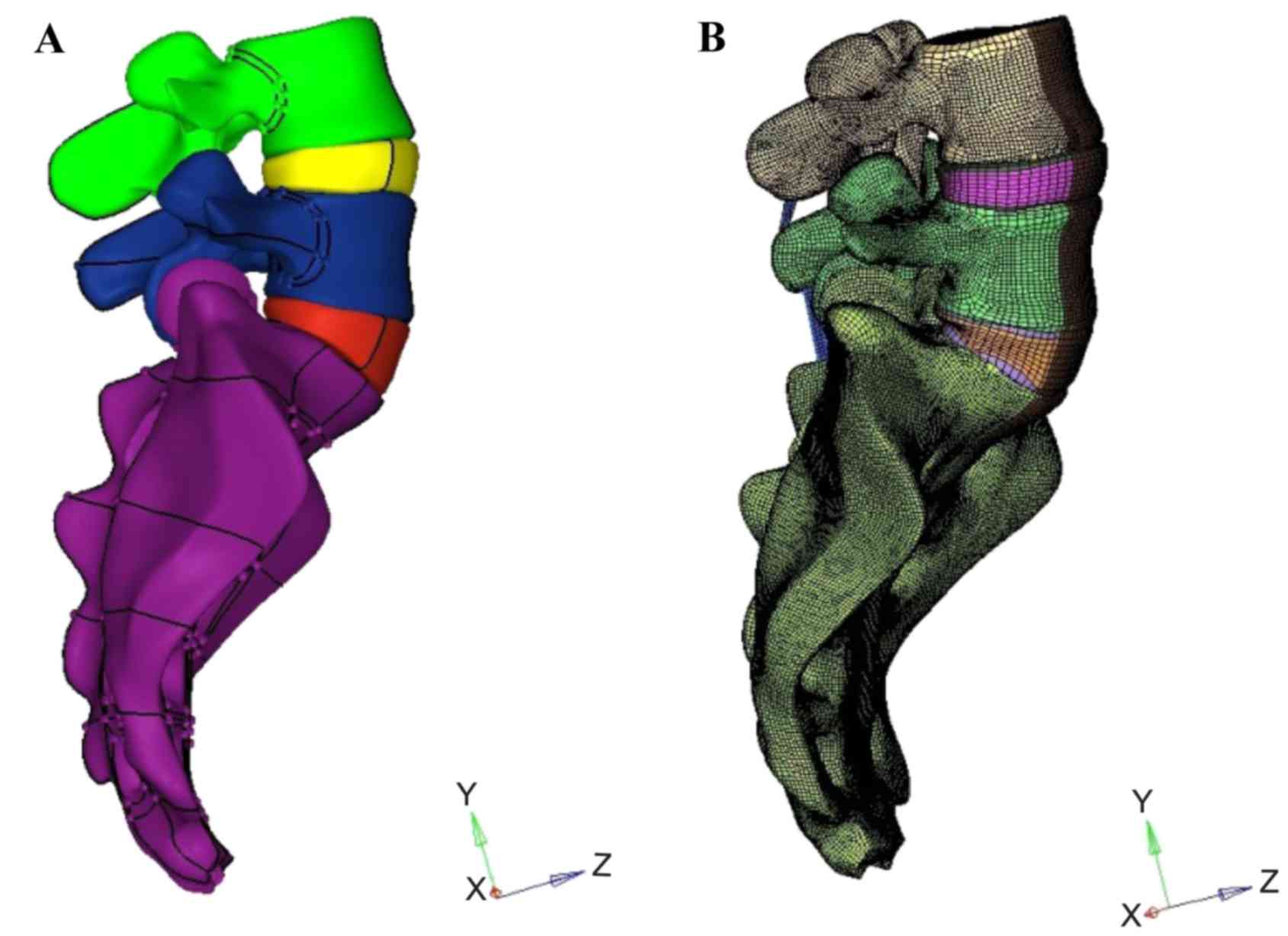
biomechanical characteristics. In the present study, a surface
model (Fig. 2A) including the L4-S1
segment was first constructed based on computed tomography (CT)
scan images of a 30-year-old healthy male volunteer with an SS of
55°. A corresponding solid model was then constructed in HyperMesh
(Altair Engineering, Inc., Troy, MI, USA). Meshing was also
implemented in HyperMesh (Fig. 2B).
Finally, biomechanical finite element analysis of the L4-S1 segment
was carried out in ABAQUS/Standard (Dassault Systèmes,
Vélizy-Villacoublay, France). The model included the vertebrae,
intervertebral discs, endplates and ligaments.
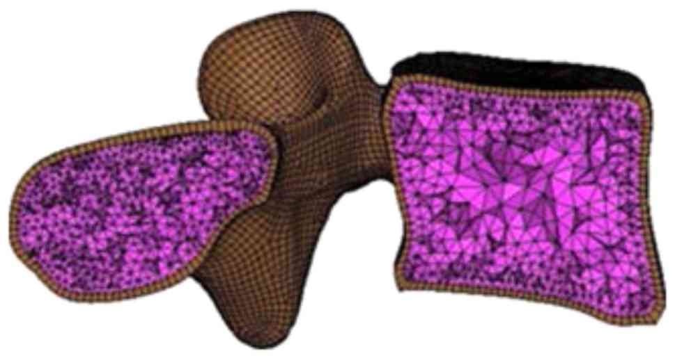
As shown in Fig. 3,
the vertebrae were divided into cortical and cancellous bones
represented by an outer layer of hexahedral solid elements and
enclosed tetrahedral solid elements, respectively. The thickness of
the cortical bones was assumed to be 1 mm (16). Notably, the nodes were shared at the
interface between cortical and cancellous bones to avoid complex
interaction problems. Bones usually exhibit a highly non-linear
biomechanical response under high loading conditions such as impact
and bone fracture (17). In current
study, as the focus was on the biomechanical behavior of the lumbar
spine under daily physiological motions, the cortical and
cancellous bones were assumed to be homogeneous and isotropic
materials with different elastic constants, as listed in Table I (18). Contact surfaces with a distance of
0.5 mm were defined to simulate the facet joints (19).
 | Table I.Properties of materials. |
Table I.
Properties of materials.
| Material | Young's modulus E
(MPa) | Poisson's ratio
ν | Element type | (Refs.) |
|---|
| Vertebrae |
|
|
|
|
|
Cortical bone | 12,000 | 0.3 | C3D8 | (18,25–30) |
|
Cancellous bone | 100 | 0.2 | C3D4 | (18,27–30) |
|
Endplate | 12,000 | 0.3 | C3D8 | (26,28,31) |
| Disc |
|
|
|
|
|
Nucleus | 1 | 0.499 | C3D8 | (29,32–34) |
| Annulus
fibrosus | User defined
material | User defined
material | C3D8 | (23) |
| Ligaments |
|
|
|
|
|
ALL | 7.8 | 0.3 | S4 | (35,36) |
|
PLL | 10 | 0.3 | S4 | (35,36) |
| LF | 15 | 0.3 | S4 | (35,36) |
| CL | 7.5 | 0.3 | S4 | (35,36) |
|
ISL | 8 | 0.3 | S4 | (35,36) |
|
SSL | 8 | 0.3 | S4 | (35,36) |
The intervertebral discs were divided into superior
and inferior endplates, annulus fibrosus and nucleus pulposus. The
endplates had a thickness of 0.5 mm (20) and were connected with their adjacent
vertebrae by sharing common nodes on the interfaces. They were
meshed by 3D solid elements and assigned a linear isotropic elastic
model with material parameters listed in Table I. For the disc, 30–50% of the
cross-section area was defined as nucleus, and the rest was
processed as the annulus fibrosus (21). The nucleus was assumed to be a nearly
incompressible material by assignment of a Poisson's ratio of 0.499
and a low Young's modulus of 1 MPa. The ROM of the human spine is
mainly affected by intervertebral discs. The constitutive model for
large deformation segments such as the annulus fibrosus is
considered to provide accurate results. The annulus fibrosus is
often characterized as fiber-reinforced materials in which several
matrix layers are embedded with rebar elements representing
collagen fibers (11,12,14,15,22). The
effect of interaction between fibers and matrix is ignored when
using the one-dimensional rebar elements method. Also, this method
increases meshing difficulty. To overcome these shortcomings, Peng
et al (23) developed a
continuum mechanics-based fiber reinforced hyperelastic model to
characterize the anisotropic nonlinear biomechanical behavior of
annulus fibrosus. The strain energy function to determine the
constitutive relationship is given as follows:
W=WM+WF+WFM
where WM, WF and
WFM are the energy contribution from ground
matrix, fiber elongation and the interaction between matrix and
fibers, respectively. The specific forms of strain energy functions
for the annulus fibrosis are given as follows:
WM=C10(I¯1–3)+1D1(J–1)2WF={0I4≤1C2(I4–1)2+C3(I4–1)4I4>1WFM=WFM(I4,ɸ)=f(I4)χ2=f(I4)[I4I3(I5–I1I4+I2)–1]2
where (I4)=γ1+exp[–β(λF–λF*)]andIi(i=1,…,5) are
principal invariants, and C10=0.034 MPa,
D1=0.197 MPa−1,
C2=0.45 MPa, C3=82.6 MPa,
γ=12.0 MPa β=125 and λ*F=1.02 are material parameters.
More detail has been provided in a previous study (). This constitutive model was
implemented by designing a user defined material subroutine
(UANISOHYPER) in ABAQUS/Standard (Dassault Systèmes). The
orientation of fibers was defined as ±30° to the horizontal plane
(,).
Ligaments play a major role in spinal stability and
function (24). A total of 6
ligaments including the anterior longitudinal ligament (ALL),
posterior longitudinal ligament (PLL), ligamentum flavum (LF),
capsular ligament (CL), interspinous ligament (ISL) and supraspinal
ligament (SSL) were modeled as isotropic linear elastic membranes
that are able to bear tensile loads only.
Material parameters for different parts of the model
are summarized in Table I.
L4-S1 models with different SS
In order to investigate the influence of SS on the
biomechanical behavior of the lumbar spine, the L4-S1 spine model
was modified with different SS. In accordance with a previous study
(4), the SS angles were divided into
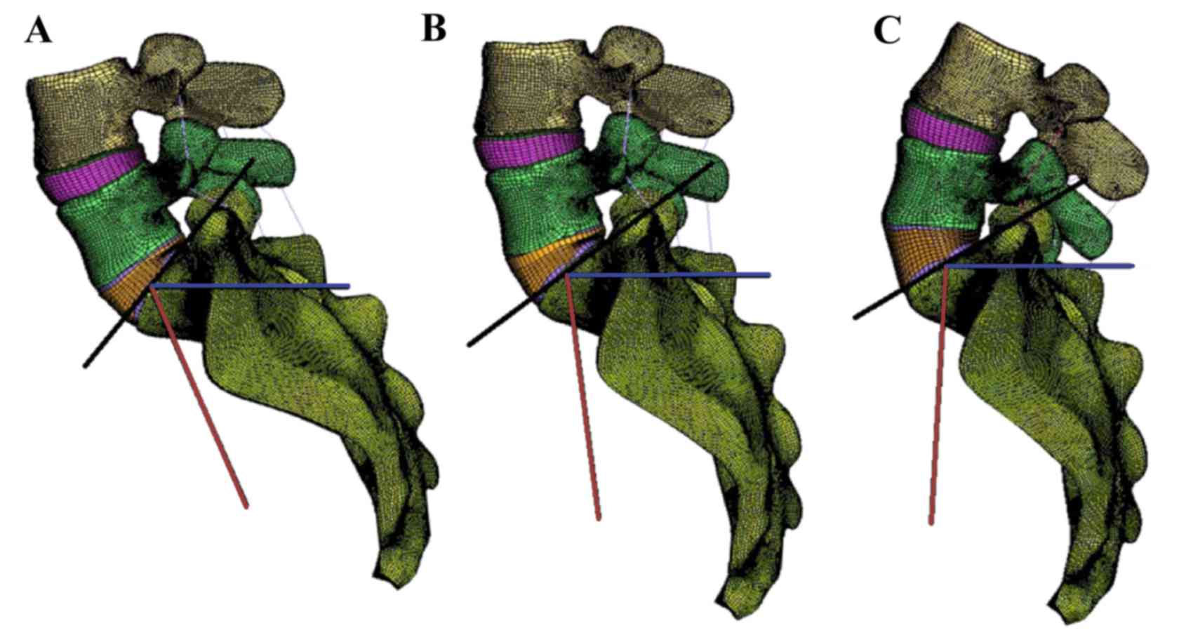
three groups: SS>45°, 35°<SS≤45° and SS≤35°. As shown in
Fig. 4, three SS angles of 55, 40
and 25° were chosen as the typical angle for each group. Noting
that the change of lumbar lordosis causes pelvis retroversion, then
influences the SS angle, the shape of the intervertebral discs was
slightly changed as shown in Fig. 4.
For convenience, models I, II and III are used for distinction.
Convergence testing was performed to filter the influence of mesh
size. The model had 260,729 nodes and 854,845 elements with an
average element size of ~0.75 mm.
Boundary and loading conditions
Considering the daily physiological actions of the
human spine, four basic motions including flexion, extension,
lateral bending and torsion were selected in numerical simulations.
S5 were completely constrained. According to the study by Yamamoto
et al (9), a 150-N vertical
axial pre-load was imposed on the superior surface of L4; at the
same time, a 10-N·m moment was applied on the L4 superior surface
along the radial direction to simulate the four basic physiological
motions.
Simulation results of the L4-S1 model with an SS of
55° under various pathological loading conditions were compared
with cadaveric test data in the literature for model validation.
Then, numerical simulations were extended to other L4-S1 models
with different SS values to investigate the effect on the
biomechanical responses of the lumbar spine.
Model validation
For model validation, ROMs under different human
physiological motions were employed as a verification criterion.
Table II lists the predicted ROMs
of the L4-S1 FE model under flexion, extension, lateral bending and
torsion, respectively with a 150-N pre-load and a 10-N·m moment.
For comparison, in vitro ROMs reported by different research
groups (6–9,36) are
also presented in Table II.
| Table II.Range of motion (°) for different
motions. |
Table II.
Range of motion (°) for different
motions.
| Study | Flexion | Extension | Lateral
bending | Torsion | (Ref.) |
|---|
| Shirazi-Adl et
al | 4.96 | 2.94 | – | – | (6) |
| Tencer et
al | 6.23 | 4.19 | – | – | (7) |
| Schultz et
al | 5.79 | 2.79 | – | – | (8) |
| Chen et
al | 5.41 | 3.13 | – | – | (36) |
| Yamamoto et
al | – | – | 3.5–4.2 | 2–2.8 | (9) |
| Present study |
|
|
|
|
|
|
SS=55° | 6.13 | 3.24 | 4.07 | 1.79 |
|
|
SS=40° | 5.70 | 3.50 | 3.72 | 2.09 |
|
|
SS=25° | 5.34 | 3.89 | 3.79 | 2.20 |
|
As shown in Table
II, the in vitro ROMs reported by different groups vary
in a range of 4.9–6.2° for flexion, and 2.8–4.2° for extension. In
the present study, the ROM was 6.13 and 3.24° for flexion and
extension, respectively. The simulation results fall into the in
vitro experimental ranges of ROMs for the two motions,
respectively. For lateral bending and torsion, the predicted ROMs
were 3.47 and 1.79°, respectively, a little bit below the in
vitro experimental ranges of ROMs, which are 3.5–4.2° for
lateral bending and 2–2.8° for torsion (9).
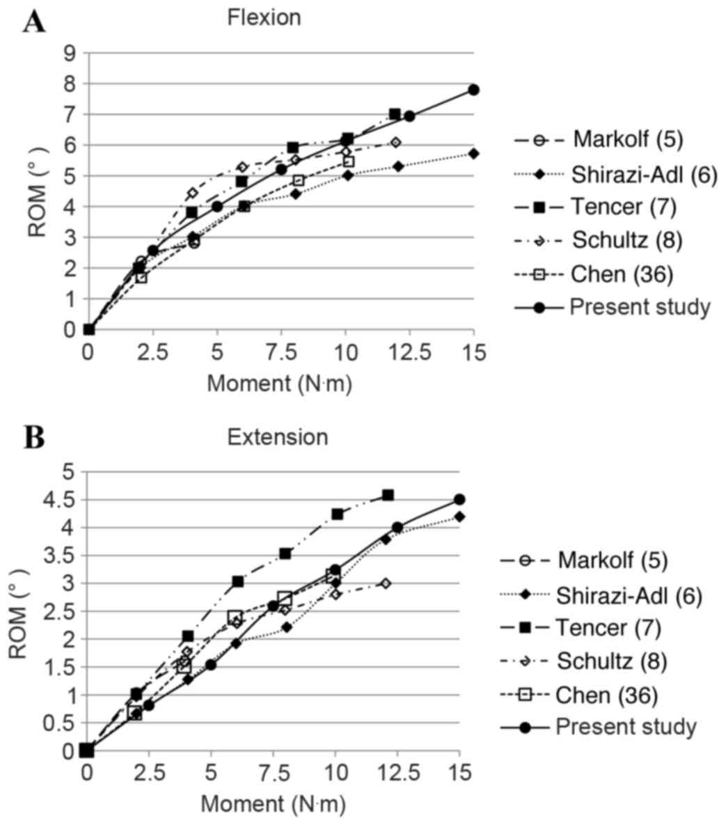
Fig. 5 shows the
in vitro experimental ROMs of the L4-S1 lumbar spine segment
under flexion and extension with different loading magnitudes from
0 to 15 N·m, respectively (5–8,36). Numerical results of the present model
are also shown in Fig. 5A for
flexion and Fig. 5B for extension by
solid lines with filled circles. As presented in Fig. 5, the simulation results are in
concordance with the experimental data, bearing in mind the
deviations of in vitro testing data from different studies.
The ROMs are nonlinear to the applied moment and render a
decreasing tendency with the increase of applied moment for both
motions.
Results and Discussion
With the lumbar spine FE model being validated, FE
analyses on L4-S1 models with an SS of 40° (model II) and 25°
(model III) were carried out for the four basic physiological
motions to investigate the effects of SS.
As shown in Table
II, under flexion with a 10-N·m moment, the predicted ROMs for
the two models were 5.70 and 5.34°, respectively. Compared with
model I which had an SS angle of 55°, the ROMs of model II and III
were decreased by 7.01 and 12.8%, respectively. By contrast, the
predicted ROMs increased with the reduction of SS angle for
extension, lateral bending and torsion, as indicated in Table II. However, almost all numerical
ROMs for the four motions from the three models fell into the in
vitro experimental ranges of ROMs.
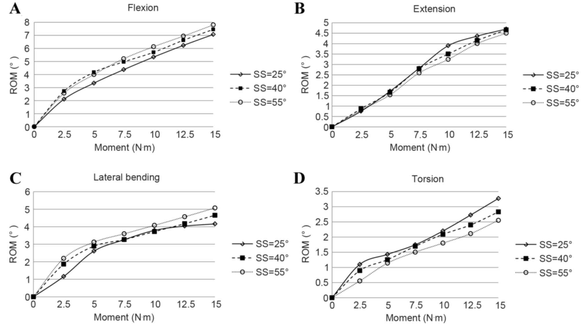
The ROMs of the three models under the four motions
with different loading moment magnitudes are presented in Fig. 6. Generally, the spine segment showed
an increased stiffness with respect to ROM with the increase of
loading moment for all four motions. Under the same moment, the ROM
increased with the increase of SS for flexion and lateral bending;
under extension and torsion, the opposite trend occurred.
As shown in Table II
and Fig. 6, the variation of ROMs
under the same loading condition with different SS was distinct.
The maximum difference of ROM was >10% for the four motions.
Therefore, the SS can influence the biomechanical behavior of the
spine markedly.
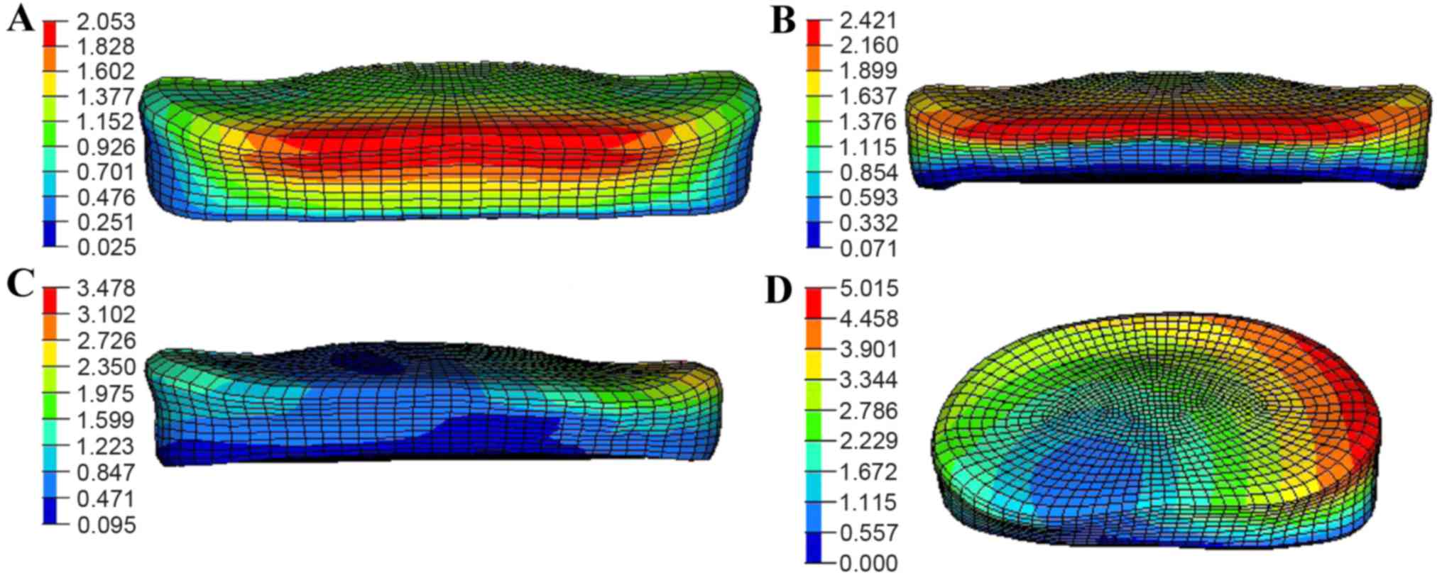
The SS affected not only the ROMs, but also the
displacement distribution of annulus fibrosus in the spine segment.
Fig. 7 shows the displacement
distribution in the L4/5-disc annulus under a 150-N pre-load and
10-N·m moment for the four motions with an SS of 55°. For flexion,
the maximum displacement was found at the border close to the upper
vertebrae segment with a magnitude of ~2.0 mm as shown in Fig. 7A. At nearly the same position, the
displacement increased to 2.4 mm for extension (Fig. 7B). The value gradually increased and
reached 3.4 mm at the compression region under lateral bending
detailed in Fig. 7C, while the peak
magnitude in all four motions occurred in torsion ~5.0 mm as
presented in Fig. 7D.
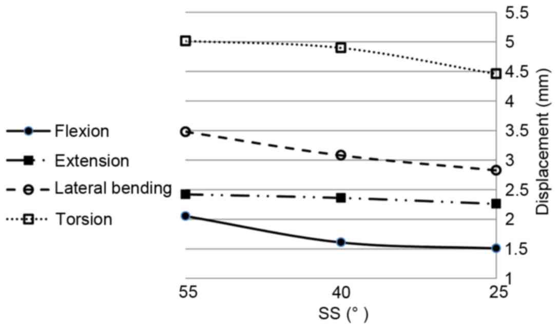
The changes of the maximum displacements in the L4/5
annulus fibrosus for the four motions with the change of SS are
shown in Fig. 8. When SS decreased,
the maximum displacement decreased for all four motions. The
maximum reduction rate was ~10, 14.3 and 25% for flexion, lateral
bending and torsion, respectively, but only 4% for extension. When
intervertebral discs degenerate with loss of lumbar lordosis,
adjacent lumbar segments are likely to compensate with the increase
of lordosis, followed by retroversion of the pelvis with the
reduction of SS, with reduction of the displacement of the annulus
fibrosus. Additionally, although it was not shown, nearly the same
displacement distribution appeared for the L5/S1 disc with maximum
values of only ~0.8, 0.5, 1.3 and 2.2 mm for flexion, extension,
lateral bending and torsion, respectively.
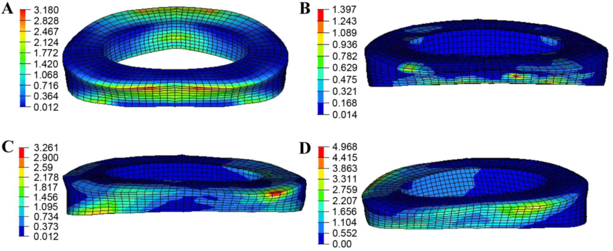
The von Mises stress distribution on the L4/5
annulus fibrosus under a 150-N pre-load and 10-N·m moment is shown
in Fig. 9. The largest stress region
appeared in the posterior side of the annulus fibrosus,
particularly in flexion, extension and lateral bending (Fig. 9A-C). For torsion, the annulus
fibrosus was twisted, so the stress mainly distributed along the
orientation of fibers with a maximum magnitude of ~4.9 MPa as
detailed in Fig. 9D.
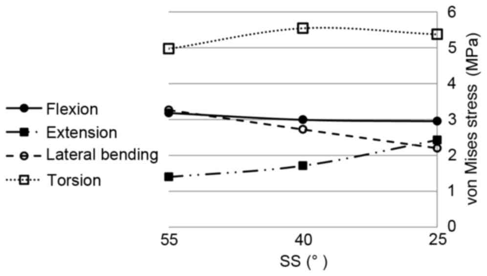
The changes of the maximum von Mises stress in the
L4/5 annulus fibrosus for the four motions with the change of SS
are shown in Fig. 10. With the
reduction of SS from 55 to 25°, the maximum von Mises stresses for
extension markedly increased from 1.3 to 2.4 MPa, an increase of
~84%. For lateral bending, the maximum von Mises stress decreased
from 3.2 to 2.2 MPa, a reduction of ~30%. For flexion, the effect
of SS was insignificant. The maximum von Mises stress fluctuated by
~3.0 MPa. For torsion, the maximum stress initially increased then
decreased with the reduction of SS ~5.3 MPa. For the L5/S1 disc,
the stresses had little change under flexion, extension and lateral
bending with magnitudes of ~1.3, 0.1 and 1.6 MPa, respectively.
However, for torsion, the stresses declined notably, and were 3.2,
1.7 and 0.9 MPa in the three models.
Briefly, when an intervertebral disc degenerates,
the spine structure compensates to keep sagittal balance by
retroversion of the pelvis with reduction of the SS. The
predictions based on FEM show that as SS decreased, the ROMs of
flexion and lateral bending reduced, and the ROMs of extension and
torsion increased. The maximum displacements reduced 10–25% in
flexion, lateral bending and torsion, but in extension the maximum
displacement only dropped 4%. Considering stress, in contrast to
flexion, the magnitudes for extension and lateral bending varied
markedly, and for torsion the value increased by ~10% initially,
then decreased with the reduction of SS. Although only the L4 to S1
segment was considered in the present model, the mechanical
responses including ROMs, displacement and stress had different
degrees of variation, according to this study, when compensation
occurred; thus, the SS did have a great influence on the
biomechanical behavior of the spine structure.
The present study has several limitations. Firstly,
the material models for ligaments and vertebrae were simplified and
idealized. Secondly, spine structural compensation often occurs
following disc degeneration (4).
However, the present study ignored the effect of disc degeneration
and only focused on the influence of SS. Thirdly, structural
compensation also influences regions other than the L4-S segment,
particularly for intervertebral discs (4). Therefore, the current spinal model
should be extended by including more spinal segments. Lastly, in
the human body, vertebrae are connected by not only ligaments, but
also by muscles, which was ignored in the current model. Our future
studies will concentrate on developing a more accurate model to
comprehend the biomechanical essentials of human spine segment.
In conclusion, in the present study a
three-dimensional finite element model of L4-S spine was
established to investigate the effect of SS on biomechanical
behavior under various daily actions, including flexion, extension,
lateral bending and torsion motions. The model was validated by
comparing simulation results with in vitro cadaveric test
data. The numerical predictions indicated that as SS decreased, the
ROMs of flexion and lateral bending reduced, and the ROMs of
extension and torsion increased. The maximum displacements of L4/5
AF reduced 10–25% in flexion, lateral bending and torsion, whereas
the displacement of extension dropped only 4%. The effect of SS on
von Mises stress of L4/5 AF was minimal in flexion, but marked in
lateral bending with a 31% drop. By contrast, the stress increased
~84% in extension. In torsion, the maximum stress initially
increased then decreased with the reduction of SS. The present
study indicated that the change of SS caused by structural
compensation affected the biomechanical behavior of the spine
structure, and attention should be paid to SS when conducting
surgical procedures or selecting intervertebral fusion
implants.
Acknowledgements
Support from the National Natural Science Foundation
of China (grant no. 11172171) and the Science and Technology
Commission of Shanghai Municipality (grant nos. 13DZ1940504 and
13DZ1940505) are gratefully acknowledged.
References
|
1
|
Duval-Beaupère G, Schmidt C and Cosson P:
A barycentremetric study of the sagittal shape of spine and pelvis:
The conditions required for an economic standing position. Ann
Biomed Eng. 20:451–462. 1992. View Article : Google Scholar : PubMed/NCBI
|
|
2
|
Duval-Beaupère G and Legaye J: Composante
sagittale de la statique rachidienne. Revue Du Rhumatisme.
71:105–119. 2004. View Article : Google Scholar
|
|
3
|
Boulay C, Tardieu C, Hecquet J, Benaim C,
Mouilleseaux B, Marty C, Prat-Pradal D, Legaye J, Duval-Beaupère G
and Pélissier J: Sagittal alignment of spine and pelvis regulated
by pelvic incidence: Standard values and prediction of lordosis.
Eur Spine J. 15:415–422. 2006. View Article : Google Scholar : PubMed/NCBI
|
|
4
|
Roussouly P and Pinheiro-Franco JL:
Biomechanical analysis of the spino-pelvic organization and
adaptation in pathology. Eur Spine J. 20 Suppl 5:S609–S618. 2011.
View Article : Google Scholar
|
|
5
|
Markolf KL: Deformation of the
thoracolumbar intervertebral joints in response to external loads:
A bomechanical study using autopsy material. J Bone Joint Surg Am.
54:511–533. 1972. View Article : Google Scholar : PubMed/NCBI
|
|
6
|
Shirazi-Adl SA, Shrivastava SC and Ahmed
AM: Stress analysis of the lumbar disc-body unit in compression. A
three-dimensional nonlinear finite element study. Spine (Phila Pa
1976). 9:120–134. 1984. View Article : Google Scholar : PubMed/NCBI
|
|
7
|
Tencer AF, Ahmed AM and Burke DL: Some
static mechanical properties of the lumbar intervertebral joint,
intact and injured. J Biomech Eng. 104:193–201. 1982. View Article : Google Scholar : PubMed/NCBI
|
|
8
|
Schultz A, Andersson G, Ortengren R,
Haderspeck K and Nachemson A: Loads on the lumbar spine. Validation
of a biomechanical analysis by measurements of intradiscal
pressures and myoelectric signals. J Bone Joint Surg Am.
64:713–720. 1982. View Article : Google Scholar : PubMed/NCBI
|
|
9
|
Yamamoto I, Panjabi MM, Crisco T and
Oxland T: Three-dimensional movements of the whole lumbar spine and
lumbosacral joint. Spine (Phila Pa 1976). 14:1256–1260. 1989.
View Article : Google Scholar : PubMed/NCBI
|
|
10
|
Shirazi-Adl A and Pamianpour M: Nonlinear
response analysis of the human ligamentous lumbar spine in
compression. On mechanisms affecting the postural stability. Spine
(Phila Pa 1976). 18:147–158. 1993. View Article : Google Scholar : PubMed/NCBI
|
|
11
|
Kuo CS, Hu HT, Lin RM, Huang KY, Lin PC,
Zhong ZC and Hseih ML: Biomechanical analysis of the lumbar spine
on facet joint force and intradiscal pressure-a finite element
study. BMC Musculoskelet Disord. 11:1512010. View Article : Google Scholar : PubMed/NCBI
|
|
12
|
Kim KT, Lee SH, Suk KS, Lee JH and Jeong
BO: Biomechanical changes of the lumbar segment after total disc
replacement: Charite(r), prodisc(r) and maverick(r) using finite
element model study. J Korean Neurosurg Soc. 47:446–453. 2010.
View Article : Google Scholar : PubMed/NCBI
|
|
13
|
Ruberté LM, Natarajan RN and Andersson GB:
Influence of single-level lumbar degenerative disc disease on the
behavior of the adjacent segments-a finite element model study. J
Biomech. 42:341–348. 2009. View Article : Google Scholar : PubMed/NCBI
|
|
14
|
Chen SH, Zhong ZC, Chen CS, Chen WJ and
Hung C: Biomechanical comparison between lumbar disc arthroplasty
and fusion. Med Eng Phys. 31:244–253. 2009. View Article : Google Scholar : PubMed/NCBI
|
|
15
|
Chen SH, Tai CL, Lin CY, Hsieh PH and Chen
WP: Biomechanical comparison of a new stand-alone anterior lumbar
interbody fusion cage with established fixation techniques-a
three-dimensional finite element analysis. BMC Musculoskelet
Disord. 9:882008. View Article : Google Scholar : PubMed/NCBI
|
|
16
|
Ritzel H, Amling M, Pösl M, Hahn M and
Delling G: The thickness of human vertebral cortical bone and its
changes in aging and osteoporosis: A histomorphometric analysis of
the complete spinal column from thirty-seven autopsy specimens. J
Bone Miner Res. 12:89–95. 1997. View Article : Google Scholar : PubMed/NCBI
|
|
17
|
Morgan EF, Yeh OC, Chang WC and Keaveny
TM: Nonlinear behavior of trabecular bone at small strains. J
Biomech Eng. 123:1–9. 2001. View Article : Google Scholar : PubMed/NCBI
|
|
18
|
Goel VK, Ramirez SA, Kong W and Gilbertson
LG: Cancellous bone Young's modulus variation within the vertebral
body of a ligamentous lumbar spine-application of bone adaptive
remodeling concepts. J Biomech Eng. 117:266–271. 1995. View Article : Google Scholar : PubMed/NCBI
|
|
19
|
Zander T, Rohlmann A, Calisse J and
Bergmann G: Estimation of muscle forces in the lumbar spine during
upper-body inclination. Clin Biomech (Bristol, Avon). 16(16 Suppl
1): S73–S80. 2001. View Article : Google Scholar : PubMed/NCBI
|
|
20
|
Silva MJ, Wang C, Keaveny TM and Hayes WC:
Direct and computed tomography thickness measurements of the human,
lumbar vertebral shell and endplate. Bone. 15:409–414. 1994.
View Article : Google Scholar : PubMed/NCBI
|
|
21
|
Panagiotacopulos ND, Pope MH, Krag MH and
Block R: Water content in human intervertebral discs. Part I.
Measurement by magnetic resonance imaging. Spine (Phila Pa 1976).
12:912–917. 1987. View Article : Google Scholar : PubMed/NCBI
|
|
22
|
Sairyo K, Goel VK, Vadapalli S,
Vishnubhotla SL, Biyani A, Ebraheim N, Terai T and Sakai T:
Biomechanical comparison of lumbar spine with or without spina
bifida occulta. A finite element analysis. Spinal Cord. 44:440–444.
2006.PubMed/NCBI
|
|
23
|
Peng XQ, Guo ZY and Moran B: An
anisotropic hyperelastic constitutive model with fiber-matrix shear
interaction for the human annulus fibrosus. J Appl Mech.
73:8152006. View Article : Google Scholar
|
|
24
|
Agur AMR and Lee MJ: Grant's atlas of
anatomy. 10th edition. Lippincott Williams & Wilkins;
Philadelphia, PA: 1999
|
|
25
|
Polikeit A, Ferguson SJ, Nolte LP and Orr
TE: Factors influencing stresses in the lumbar spine after the
insertion of intervertebral cages: Finite element analysis. Eur
Spine J. 12:413–420. 2003. View Article : Google Scholar : PubMed/NCBI
|
|
26
|
Pitzen T, Geisler FH, Matthis D,
Müller-Storz H, Pedersen K and Steudel WI: The influence of
cancellous bone density on load sharing in human lumbar spine: A
comparison between an intact and a surgically altered motion
segment. Eur Spine J. 10:23–29. 2001. View Article : Google Scholar : PubMed/NCBI
|
|
27
|
Natarajan R and Andersson G: Modeling the
annular incision in a herniated lumbar intervertebral disk to study
its effect on disk stability. Computers Structures. 64:1291–1297.
1997. View Article : Google Scholar
|
|
28
|
Denoziere G: Numerical modeling of a
ligamentous lumbar motion segment. MSc DissertationGeorgia
Institute of Technology 2004
|
|
29
|
Sairyo K, Goel VK, Masuda A, Vishnubhotla
S, Faizan A, Biyani A, Ebraheim N, Yonekura D, Murakami R and Terai
T: Three-dimensional finite element analysis of the pediatric
lumbar spine. Part I: Pathomechanism of apophyseal bony ring
fracture. Eur Spine J. 15:923–929. 2006. View Article : Google Scholar : PubMed/NCBI
|
|
30
|
Panjabi MM, Oxland TR, Yamamoto I and
Crisco JJ: Mechanical behavior of the human lumbar and lumbosacral
spine as shown by three-dimensional load-displacement curves. J
Bone Joint Surg Am. 76:413–424. 1994. View Article : Google Scholar : PubMed/NCBI
|
|
31
|
Wilke HJ, Neef P, Caimi M, Hoogland T and
Claes LE: New in vivo measurements of pressures in the
intervertebral disc in daily life. Spine (Phila Pa 1976).
24:755–762. 1999. View Article : Google Scholar : PubMed/NCBI
|
|
32
|
Rohlmann A, Zander T, Schmidt H, Wilke HJ
and Bergmann G: Analysis of the influence of disc degeneration on
the mechanical behaviour of a lumbar motion segment using the
finite element method. J Biomech. 39:2484–2490. 2006. View Article : Google Scholar : PubMed/NCBI
|
|
33
|
Ng HW and Teo EC: Nonlinear finite-element
analysis of the lower cervical spine (C4-C6) under axial loading. J
Spinal Disord. 14:201–210. 2001. View Article : Google Scholar : PubMed/NCBI
|
|
34
|
Smit TH, Odgaard A and Schneider E:
Structure and function of vertebral trabecular bone. Spine (Phila
Pa 1976). 22:2823–2833. 1997. View Article : Google Scholar : PubMed/NCBI
|
|
35
|
Pitzen T, Geisler F, Matthis D,
Müller-Storz H, Barbier D, Steudel WI and Feldges A: A finite
element model for predicting the biomechanical behaviour of the
human lumbar spine. Control Engineering Practice. 10:83–90. 2002.
View Article : Google Scholar
|
|
36
|
Chen CS, Cheng CK, Liu CL and Lo WH:
Stress analysis of the disc adjacent to interbody fusion in lumbar
spine. Med Eng Phys. 23:483–491. 2001. View Article : Google Scholar : PubMed/NCBI
|