Introduction
Minimally invasive plate osteosynthesis (MIPO) has
been broadly applied clinically following the improved
understanding of the blood supply and local biological environment
of fractures. With the development of clinical technology in China,
MIPO technology has gradually matured. It is a new development for
internal fixation using biological osteosynthesis (BO), in which
direct exposure of the fracture site is not necessary. MIPO
involves indirect reduction and fixation, which minimizes regional
damage to soft tissues and the blood supply of the periosteum, as
well as the incidence of nonunion and infection, and so is
beneficial with regard to functional rehabilitation and clinical
therapeutic effects (1).
The principle of MIPO is biological fixation at the
near- and far-ends of the fracture site (2,3). It has
a number of advantages compared with traditional open reduction and
internal fixation, and intramedullary nail fixation. Firstly, it
has a relatively short surgery time (4,5).
Secondly, it effectively avoids complications (6,7).
Thirdly, it avoids nerve damage and reduces scarring. Fourthly, it
exhibits strong healing effects (8,9).
Fifthly, it effectively reduces damage of the soft tissues and
protects the blood supply of the fracture site (10). Finally, it is able to endure large
deformation forces (11).
However, there are many contentious aspects of MIPO
application in the treatment of tibial fractures, particularly the
length of the limited contact-dynamic compression plate (LC-DCP),
the number of screws and the fixing positions, and there are no
clear conclusions with regard to the optimum parameters.
Therefore, in the present study 60 tibias from
cadavers were used for the examination of tibial fractures by
biomechanical and finite element analysis, in order to provide
evidence regarding the treatment of middle tibial fractures using
MIPO with BO.
Materials and methods
Materials
Biomechanical testing
Wet tibial samples (n=60) were collected from
cadavers from individuals with an age at mortality of 20–40 years
at the Department of Human Anatomy of Xiangya School of Medicine,
Central South University (Changsha, China). Ethical approval was
obtained from the institution. The tibias were inspected and X-ray
examination was performed, in order to exclude damage and bone
pathology, prior to storage at −20°C. The fixation materials,
namely 6-hole LC-DCPs (model 4.5; length, 105 mm, width, 8 mm;
thickness, 3.5 mm), 10-hole LC-DCPs (model 4.5; length, 178 mm;
width, 8 mm; thickness, 3.5 mm), 14-hole LC-DCPs (model 4.5;
length, 250 mm; width, 8 mm; thickness, 3.5 mm), cortical stainless
steel bone screws (Φ, 4.5 mm), and AO internal fixing equipment
were obtained from Bangli Trading Co. (Yangjiang, China).
3D finite element analysis
Five tibias 30–38 cm in length (mean, 34 cm) were
collected from the Department of Human Anatomy of Xiangya School of
Medicine, Central South University. The other materials used were
the same as those described above.
Analytical instrumentation
Biomechanical testing
The MTS 858 Mini Bionix universal biomechanics
testing system (MTS Systems Corporation, Eden Prairie, MN, USA) was
supported by the Department of Human Anatomy of Southern Medical
University.
Three-dimensional (3D) finite element
analysis
Analysis was conducted using spiral computed
tomography (CT), a computer, AutoCAD software (Autodesk, Inc., San
Rafael, CA, USA) and finite element software Ansys 6.5.
Biomechanical testing methods
Middle and diagonal fracture models without defects
were established using the collected tibias. The tibias were
randomly grouped and analyzed by biomechanics and 3D finite element
methods. An analysis and comparison of LC-DCPs with different
lengths (6-, 10- and 14-hole) combined with 6 screws, 14-hole
LC-DCPs combined with different numbers of screws (6, 10 and 14),
and 14-hole LC-DCPs with 6 screws fixed at different positions was
conducted. The positions fixed were as follows (from top to
bottom): Group 1, holes 1, 2, 7, 8, 13 and 14; group 2, holes 1, 4,
7, 8, 11 and 14; group 3, holes 1, 3, 6, 9, 12 and 14; and group 4,
holes 1–3 and 12–14. Mechanical characteristics, including
compression, torsion and 3-point bending, respectively, were
evaluated. The load of vertical compression was 0–1,000 N, the
torsion angle was 0–3°, and the load of 3-point bending was 0–400
N. The strain values on torsion, and with 3-point bending and
compression were measured and analyzed.
3D reconstruction of tibial stem finite element
models. The tibias were scanned using spiral CT and continuous
cross-sectional images 1 mm in thickness were obtained. The images
were analyzed as lattice images and digitized. Using a graphic
boundary automatic recording program, created by the Laboratory of
Human Anatomy and Biomechanics of Southern Medical University
(China), the boundary conditions of the images were recorded as 2D
coordinates in all levels of the tibial images according to the
requirements for 3D reconstruction. With reference to the plane
distance and inter-lamellar space, the 2D coordinates were
converted into 3D coordinates following regulation to a suitable
spatial scale.
The mechanical values of the tibial materials were
searched and switched using the AutoCAD modeling software. The
middle tibial fracture model was established with internal fixation
using 3D Max.
Using the finite element software Ansys 6.5, the 3D
tibial spatial model was established according to modeling
principles on points, lines, regions and bodies from top to bottom.
CT scanning was conducted in cross-sectional directions in parallel
with the xy plane, with the longitudinal direction along the
z-axis.
In the digital tibia models, there were 265
reconstruction levels in total. The z-axis was established
according to the actual height. The corresponding junctions were
connected in each level and geometric models of the tibias were
formed. Different colors were used to distinguish different levels
and structures, and the element was then divided into different
gridding.
3D reconstruction of MIPO-treated
middle tibia fractures
Establishing middle tibial fractures with
internal fixation
Five tibias were used to create middle and diagonal
fracture models without defects. They were tilted 45° from the
tibial eminence backwards, with an average slope length of 35 mm. A
14-hole LC-DCP and 6 screws were used for fixation, with the
fracture line at the middle of the plate. From top to bottom, the
fixing positions were as follows: Tibia-1 model, 1st, 2nd, 3rd,
12th, 13th and 14th holes; tibia-2 model, 1st, 4th, 7th, 8th, 11th
and 14th holes; tibia-3 model, 1st, 3rd, 6th, 9th, 12th and 14th
holes; tibia-4 model, 1st, 2nd, 7th, 8th, 13th and 14th holes. In
the tibia-5 model, all 14 holes were fixed with screws.
3D reconstruction of tibial fractures with
internal fixation
The fixed tibias were scanned by spiral CT and
continuous cross-sectional images of 1 mm thickness were obtained.
The images were analyzed as lattice images, digitized and used to
establish digital tibia models with 265 reconstruction levels as
described above.
Loading the digital model of middle tibia
fracture internal fixation
The tibia-1 model with fixation positions at the
1st, 2nd, 3rd, 12th, 13th and 14th holes was loaded. i) Fixation of
the digital model was simulated. According to the anatomical
structure and biomechanical characteristics of the tibia, a 14-hole
plate and 6 screws were used for digital tibia model fixation. ii)
Axial compression of the digital model was detected. Following
fixation of the digital middle tibial fracture model with a 14-hole
plate and 6 screws, the LC-DCP was compressed with a load of
0–1,000 N vertically and evenly. Data were collected and the
vertical and lateral strain values were obtained. Data were
analyzed with the load of 1,000 N. iii) Torsion of the digital
model was detected. Following fixation of the digital middle tibial
fracture model with a 14-hole plate and 6 screws, torsional
stiffness of the left and right directions was detected using a
torsion rate of 2°/sec and angle of 3°. The torque was obtained
from the collecting system and analyzed statistically.
The tibia-2, −3, −4 and −5 models were each loaded
and analyzed according to the procedure described above.
Statistical analysis
All data were collected automatically and analyzed
using SPSS 12.0 software (SPSS, Inc., Chicago, IL, USA). Analysis
of variance was employed for pairwise comparisons, followed by
Tukey's post hoc testing. P<0.05 was considered to indicate a
statistically significant difference.
Results
Biomechanical effects of LC-DCP length
on middle tibial fractures
For vertical compression, the strain values for 6-,
10- and 14-hole LC-DCPs were 0.449±0.241, 0.093±0.003 and
0.139±0.005, respectively. The strain values for the 10- and
14-hole plates were significantly lower than those for the 6-hole
plate (P<0.01). The lateral strain values for 6-, 10- and
14-hole LC-DCPs were 0.120±0.000, 0.1275±0.010 and 0.237±0.000,
respectively. The lateral strain values for the 6- and 10-hole
LC-DCPs were significantly different from those for the 14-hole
LC-DCP (P<0.01); however, no significant difference was
identified between 6- and 10-hole LC-DCPs (P>0.05). The torques
of the 6-, 10- and 14-hole LC-DCPs were
5.066×10⁻³±2.715×10⁻³,
5.671×10⁻³±2.527×10⁻³ and
4.570×10⁻³±2.228×10⁻³ N·m, and the vertical
strain values of 3-point bending were 0.049±0.009, 0.124±0.017 and
0.062±0.009, respectively. Pairwise comparisons for LC-DCPs of
different lengths identified significant differences
(P<0.05).
Biomechanical effects of screw number
on middle tibial fractures
For vertical compression using 14-hole LC-DCPs, the
strain values for 6, 10 and 14 screws were 0.120±0.006, 0.111±0.012
and 0.116±0.008, respectively, with no significant difference
revealed by pairwise comparisons (P>0.05). The lateral strain
values for 6, 10 and 14 screws were 0.234±0.007, 0.234±0.000 and
0.179±0.002, respectively, without significant differences revealed
by pairwise comparisons (P>0.05). The torques for 6, 10 and 14
screws were 7.304×10⁻³±3.072×10⁻³,
6.069×10⁻³±3.086×10⁻³ and
7.1295×10⁻³±3.908×10⁻³ N·m, respectively,
without significant differences indicated by pairwise comparisons
(P>0.05). The vertical strain values of 3-point bending for 6,
10 and 14 screws were 0.149±0.098, 0.139±0.003 and 0.258±0.001,
respectively; the vertical strain values for 6 and 10 screws were
was significantly different from those for 14 screws (P<0.01),
while no significant difference was identified between 6 and 10
screws (P>0.05).
Biomechanical effects of fixing
positions on middle tibial fractures
For groups 1–4, the strain values of vertical
compression were 0.120±0.006, 0.033±0.003, 0.139±0.005 and
0.116±0.008, respectively, with significant differences between
group 2 and the other groups (P<0.01). The lateral strain values
in the four groups were 0.234±0.007, 0.237±0.0006, 0.187±0.002 and
0.217±0.002, respectively, with significant differences between
group 3 and the other groups (P<0.01). The torques were
7.304×10⁻³±3.072×10⁻³,
6.965×10⁻³±3.096×10⁻³,
4.570×10⁻³±2.228×10⁻³ and
2.086×10⁻³±0.998*10−3 N·m, respectively, with
significant differences identified between group 3 and the other
groups (P<0.01). The strain values of 3-point bending in the
four groups were 0.149±0.098, 0.184±0.002, 0.004±0.001 and
0.282±0.000, respectively. Values for groups 3 and 4 were indicated
to be significantly different compared with group 1 or 2 by
pairwise comparison (P<0.01). Group 4 was indicated to be
significantly different from the other groups by pairwise
comparisons (P<0.01). However, there was no significant
difference between groups 1 and 2 (P>0.05).
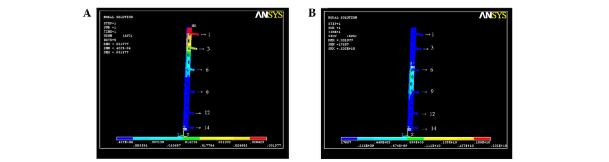
Stress sustained in the tibia-1
model
For axial compression, the compression and torsion
at the 3rd and 12th holes on the x- and y-axes were the greatest,
and accumulated on the fracture. There was no significant
difference in the stress on the z-axis among the various screw
positions. Thus, the stress on any individual screws was minimized.
The main strain was focused on the positions without fixation
(Fig. 1).
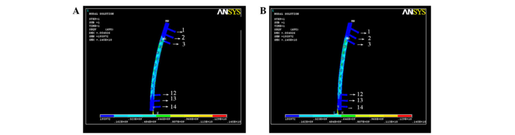
Stress sustained in the tibia-2
model
For axial compression, the stress on the 1st hole on
the x-, y- and z-axes was the greatest, followed by the 4th hole.
The stress decreased gradually from the top to the bottom of the
plate. With regard to torque, the stress on the 7th and 8th holes
on the x-, y- and z-axes was the greatest, and the stress tended to
decrease gradually from the middle of the fracture to the end. The
stress was mainly focused on the center of the plate (Fig. 2).
Stress sustained in the tibia-3
model
For axial compression, the stress on the 1st hole on
the x-, y- and z-axes was the greatest, followed by the 3rd hole.
The stress decreased gradually from the top to the bottom of the
plate. For torque, the stress on the 6th and 9th holes on the x-,
y- and z-axes was the greatest, with the greater strain on the
center without fixation (Fig.
3).
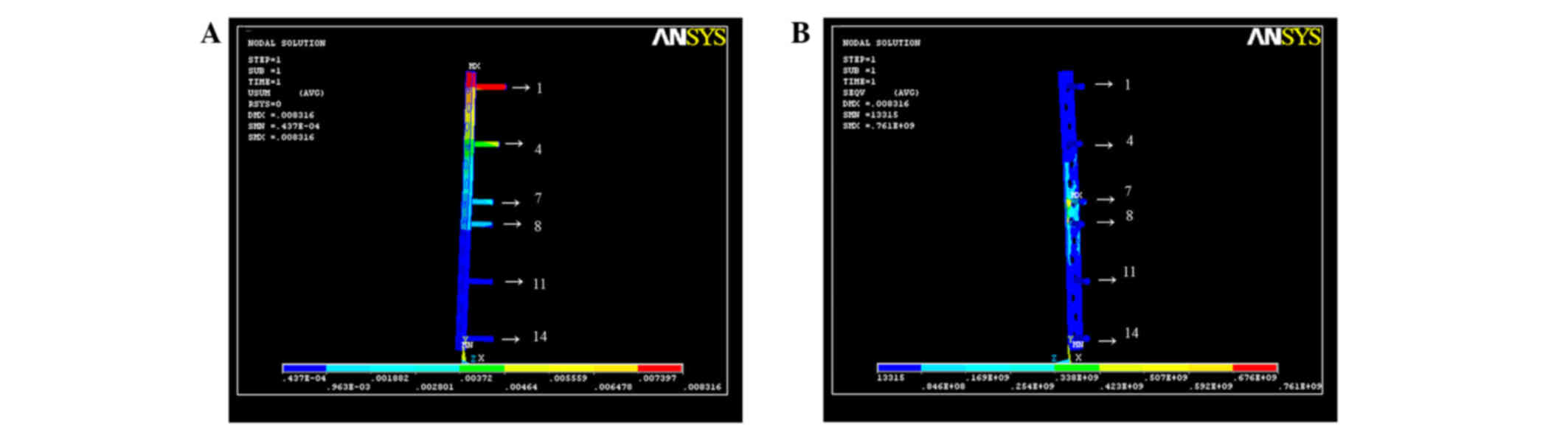
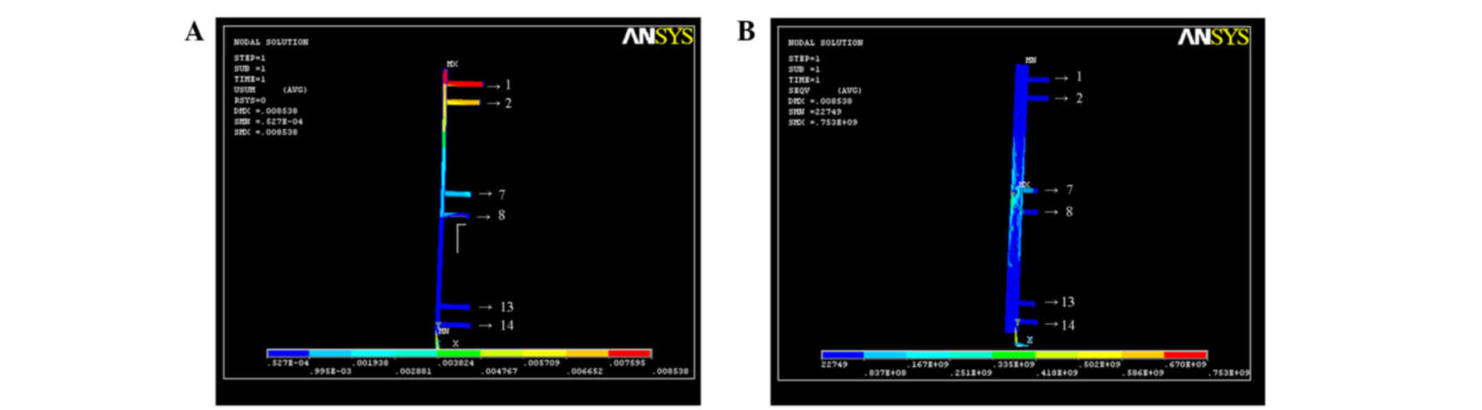
Stress sustained in the tibia-4
model
For axial compression, the stress on the 1st hole on
the x-, y- and z-axes was the greatest. The stress decreased
gradually from the top to the bottom of the plate. With regard to
torque, the stress on the 7th and 8th holes on the x-, y- and
z-axes was the greatest, but less than in the tibia-3 model, with a
balanced strain distribution (Fig.
4).
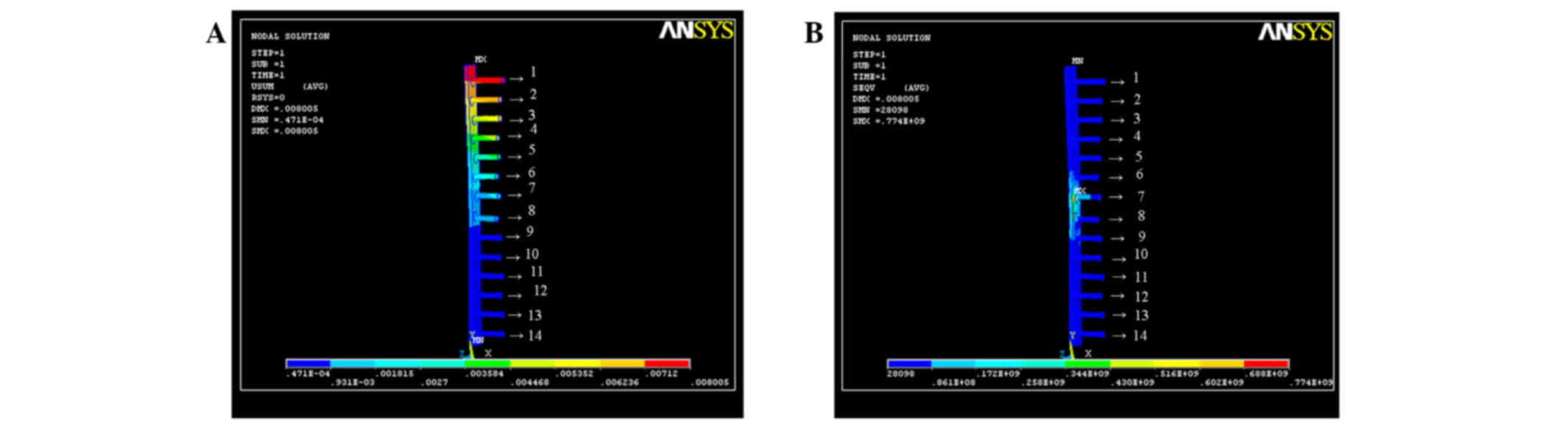
Stress sustained in the tibia-5
model
For axial compression, the stress on the 1st hole on
the x-, y and z-axes was the greatest, followed by the 2nd hole.
The stress decreased gradually from the top to the bottom of the
plate. For torque, the stress on the 7th and 8th holes on the x-,
y- and z-axes was the greatest. The strain was particularly focused
on the two screws in the center of the LC-DCP (Fig. 5).
Discussion
As increases in the energy or speed of damage have
occurred, for example, in traffic accidents, the incidence of
tibial fractures has notably increased; such fractures account for
10% of long bone fractures (12).
Tibial fractures are predominantly middle fractures (13–17).
Therefore, further investigations focused on middle tibial
fractures are warranted.
On the basis of the BO concept, investigations on
MIPO in the treatment of fractures have been performed and
therapeutic effects obtained. MIPO is a novel development for the
treatment of fractures, and has been conducted as follows: For
indirect reduction, a small incision was opened distally to the
fracture; a subcutaneous tunnel was established and the LC-DCP was
embedded with fixation (18,19). For broken ends of fractured bone
without exposure, the integrity of the soft tissue between the
broken ends of fracture bone was maintained thoroughly (20). The integration of soft tissue around
the fractured bone provides the healing with beneficial biotic
environment as an important co-factor for correcting and sustaining
the bone after fixation.
Numerous models have been used in orthopedic
biomechanics research, such as animal models, physical models,
cadaveric models and finite element analysis. However, there are
certain limitations for each kind of model (21–23).
Cadaveric models are advantageous in geometrical structure and
material characteristics, and are the most appropriate for
providing values on biomechanical properties, which are used in
surgery for evaluation; however, they lack certain biological
features, have higher experimental expense, may be difficult to
acquire and have low potential for repeated use, limiting their
application (24,25). Finite element analysis is a
repeatable and sustainable method of research, and is a relatively
novel method for studying orthopedic biomechanics. Finite element
analysis is able to reflect interactions regionally and internally,
with changes in subjective and material structures, in order to
provide a biomechanical evaluation and prognosis for different
kinds of disease and injury, fixture equipment and surgical methods
(26,27). Finite element analysis in the
biomechanical simulation of internal fracture fixation has been
widely used, in China and elsewhere. However, due to the complexity
of finite element analysis, particularly establishment of the
model, its application in orthopedic biomechanics is limited, with
confirmation between the results and the practical experiments
being necessary. Therefore, in the present study, biomechanics
combined with finite element analysis was used to mutually confirm
the results of MIPO in the treatment of tibial fractures, in order
to provide theoretical evidence for clinical treatment.
He et al (28)
studied the effects of screw number on the load of internally fixed
structures using a torsion test. Combining their observations with
those reported in the literature, they summarized that omitting 40%
of the screws of an LC-DCP had no significant effect on the
stiffness for one plate with internal fixation. Therefore, in the
present study, two positions at the ends of the LC-DCP were fixed,
in order to exclude the effect of length on internal stability.
In the analysis of screw breakage in steel plates
used to treat middle long bone fractures, Liu et al
(29) found that in addition to
anatomical restoration, stability was also critical in internal
fixation. It was considered that the stability of fractures was
associated with the length of the fixing material, which demanded
that the plate length was 5 times as long as the longest fracture
line and ≥4 cortices were fixed at one side of an ulnoradial
fracture, 6–8 cortices of a humeral fracture, and 8–10 cortices of
the tibial or femoral fracture. However, according to the study by
Laurence et al (19), 4
screws were sufficient for fixation of one plate with mechanical
stability. Rozbruch et al (20) recommended that the screws should be
fixed at the most appropriate position, and for one fracture
fragment, there should be 2 or 3 screws for fixation, where the
most appropriate position for fixation should enhance the
connection between the steel plate and the fracture site, to
provide a stable leverage effect. Thus, a 3-point and 6-screw
method, which involved fixing the ends of the steel plate with 2
screws and fixing the ends close to the fracture line with 1 screw,
could form lever balance fixation with 3 points. On the basis of
the analysis described above, a 14-hole LC-DCP was used for the
tibial fracture test in the present study. The long plate should be
able to correct rotation and angling deformities, and sustain the
tibial axis and length. By lengthening the plate, for example, by
prolonging the lever arm for increasing the strain distribution
instead of focusing on one position, the plate, screws, bone and
soft tissues could be combined into a mechanical structure with
greater stability.
The results of the present study showed that with
the same number of screws, increasing the plate length increased
the fixing stability. By analysis of the biomechanical stability,
it was identified that a long plate was better than a short one.
With the same plate length (14-hole LC-DCP), the stability against
bending was decreased as the screw number was increased to 14, but
it was unclear whether an excessive number of screws leads to a
reduction of overall stability. Field et al (30) found there was no significant
difference in the stability of the internal fixation structure
between a steel plate in which some holes had no screws and the
same steel plate in which all holes had screws. It has been
suggested that increasing the span between the 2 screws at the ends
of the plate contributed to higher stability than a plate with
shorter span and more screws (31).
A longer plate could eliminate the use of 40% of the screws, and
increased surface tension and bone healing promotion effects were
obtained without effect on fixation. Decreasing the number of
screws may reduce skeletal trauma. More importantly, increasing the
span between screws may neutralize the external instant stress on
the screws when they are extracted.
Ellis et al (27) found that for plates of the same
length, fixation with screws at the ends of the plate increased the
stiffness against torsion. Another previous study (32) showed that with the same plate length
and number of screws, the stability against bending was improved by
distributing the screws evenly, while it was reduced by
distributing the screws at the ends of the plate. In the present
study, a plate with the same material, length, width and number of
screws was used, and the fixing position was changed. The vertical
compression test showed that with the same plate length and screw
number, the stability against compression with fixation close to
the fracture line was optimum. The torsion test showed that with
the same plate length and screw number, the stability against
torsion with fixation close to the fracture line or with even
distribution was better that than when fixing screws were
distributed at the ends of the plate.
Finite element analysis is able to break up the
whole fracture and fixation system into parts, and combine the
parts into a whole. The basic principles are as follows: Breaking
up the bone sample continuous elastomer into finite elements;
connecting the elements with junctions and evaluating the
combination instead of the bone sample primary elastomer. The
unknown values of a point in the element are analyzed through
differences in the functional relationship selected by the number
of junctions. In the analysis of the element, for the simple
element shape, complex formulas between the junctions are
established. The formulas are combined into a general formula and
the boundary conditions added. The characteristics of each element
and the whole can then be investigated. The more compact the
element distribution, the more accurate the calculation, and the
higher the quantity of work (21–23).
In the present study, the tibias were scanned by CT
and data were collected. Therefore, the models used actual geometry
to create ideal models. The 3D tibial fracture model was
reconstructed based on the direct measurements made from images of
the real sample obtained by spiral CT scanning. The reconstructed
models were vivid and objective, were able to reflect the real
geometry and biomechanical characteristics of the tibia, and
enabled the application of finite element analysis for
biomechanical study of the tibia. In this study, we compensated for
the deficiency of the finite element analysis on lower body
mechanics, and supplied new basic models and ideas to analyze the
mechanical characteristics of tibias.
A complete 3D tibial model was constructed, which
was collected from scanning images 1 mm in thickness. There were a
total of 265 levels in the reconstruction of the tibial fracture
model with internal fixation. The z-axis was constructed according
to the real height of the tibia. The junctions were connected in
each level and the different levels and structures were
distinguished with different colors.
This study was successful in 3D tibial fracture
model reconstruction and finite element analysis using Ansys
software. However, due to the limited time available for the study,
only 3D finite element models of tibias were constructed. In future
studies, 3D finite element models of the knee and ankle are
required for further investigations.
With regard to the finite element analysis, the
results showed that when the mathematical model of tibia was fixed
with a load of 1,000 N, there was significant difference in the
strain distribution only between the tibia-5 model (14 screws) and
tibia-1 model (6 screws fixed at the 1st, 2nd, 3rd, 12nd, 13th and
14th holes), while there were no significant differences among the
tibia-2 (screws at the 1st, 4th, 7th, 8th, 11th and 14th holes),
tibia-3 (screws at the 1st, 3rd, 6th, 9th, 12th and 14th holes) and
tibia-4 (screws at the 1st, 2nd, 7th, 8th, 13th and 14th holes).
When testing the stability against torsion, the strain on the
middle of the plate with 14 screws was higher compared with that
for 6 screws in tibia-2, −3 and −4 models.
When different fixing positions were used, it was
found that the strain of a 1,000-N axial load was focused on the
screws at the center of the plate, with a gradually decreasing
trend from top to bottom. These results indicated that with the
axial load, the upper screws were easily compressed and broken,
which was consistent with the mechanism of clinical LC-DCP plating
and screw breakage.
Additionally, it was also found that the strain was
the largest when the screws were fixed distal to the fracture
(tibia-1 model), which was significantly different compared with
the other 6-screw models (tibia-2, tibia-3 and tibia-4 models).
Therefore, it is not recommended that the screws are distributed at
the ends of the plate in the MIPO treatment of tibial
fractures.
For the middle fracture, when 6 screws were used for
fixation in the tibia-2, tibia-3 and tibia-4 models, the results
showed that the tibia-4 model exhibited the greatest stability
against torsion.
The biomechanical results of the present study
demonstrated that using a long LC-DPC but fewer screws for fixation
of middle tibial fractures had superior biomechanical effects
In conclusion, the use of a 14-hole LC-DCP and with
6 screws for the treatment of middle tibial fractures via MIPO is
the most appropriate. The smallest strain per screw is obtained
when 2 screws are fixed close to the fracture line (one above and
one below the fracture), and a further 4 screws are fixed at the
ends of the plate (in the 1st, 2nd, 7th, 8th, 13th and 14th
holes).
References
|
1
|
Farouk O, Krettek C, Miclau T,
Schandelmaier P, Guy P and Tscherne H: Minimally invasive plate
osteosynthesis: does percutaneous plating disrupt femoral blood
supply less than the traditional technique? J Orthop Trauma.
13:401–406. 1999. View Article : Google Scholar : PubMed/NCBI
|
|
2
|
Huang CJ, Zhang YP and Meng SM: Treatment
of humerus fractures by closing reduction with locking compression
plate through a proximal modified incision. Gu Ke. 5:111–112.
2014.(In Chinese).
|
|
3
|
Tong W, Yang J, Zhu YJ, Xu PL and Shao JK:
Minimally invasive percutaneous locking plate osteosynthesis for
treatment of osteoporotic humeral fractures in the elderly. Lin
Chuang Gu Ke Za Zhi. 5:718–720. 2014.(In Chinese).
|
|
4
|
Feng T: Fixation with intramedullary nail
and plate in the treatment of adult humeral shaft
fracture:comparison of radial nerve injury and non-union rate.
Zhongguo Zu Zhi Gong Cheng Yan Jiu Yu Lin Chuang Kang Fu.
29:2086–2090. 2015.(In Chinese).
|
|
5
|
Zhang ZZ, Xiong Y and Zhao F: The clinical
research of new fixation system for treatment of multi-segmental
fractures of humerus. Zhongguo Yi Xue Chuang Xin. 27:135–138.
2014.(In Chinese).
|
|
6
|
Shen J, Yuang TZ, Chen DD, Chang LP and Ma
PG: Clinical efficacy of locking compression plate (LCP) with
minimally invasive approach in the treatment of humerus thrypsis.
Zhongguo Dang Dai Yi Yao. 21:182–183. 2014.(In Chinese).
|
|
7
|
Ma XC, Fu DZ, Lin S, Han YJ, Chen XL, Chen
SF, Pu FF and Shao ZW: Clinical research of the minimally invasive
percutaneous plate osteosynthesis for proximal humeral fractures.
Shiyong Gu Ke Za Zhi. 20:102–105. 2014.(In Chinese).
|
|
8
|
Niu XQ, Liu FY and Guo YC: Comparison of
three different devices for humeral shaft fracture. Zhonghua Shi
Yong Zhen Duan Yu Zhi Liao Zazhi. 28:869–870. 2014.(In
Chinese).
|
|
9
|
Huang Y, Xiang M, Hu XC, Chen H, Tang HZ
and Yang GY: Application of minimally invasive locking compression
plate in treatment of hypertrophic nonunion of humeral shaft
fracture for conservative treatment failure. Sichuan Yi Xue.
6:838–841. 2015.(In Chinese).
|
|
10
|
Morgan SJ and Jeray KJ: Minimally invasive
plate osteosynthesis in fractures of the tibia. Oper Tech Orthop.
11:195–204. 2001. View Article : Google Scholar
|
|
11
|
Gösling T, Schandelmaier P, Marti A,
Hufner T, Partenheimer A and Krettek C: Less invasive stabilization
of complex tibial plateau fractures: a biomechanical evaluation of
a unilateral locked screw plate and double plating. J Orthop
Trauma. 18:546–551. 2004. View Article : Google Scholar : PubMed/NCBI
|
|
12
|
Nobert N, Moremi N, Seni J, Ramesh DM,
Ngayomela IH, Mshana SE and Gilyoma JM: The effect of early versus
delayed surgical debridement on the outcome of open long bone
fractures at Bugando Medical Centre, Mwanza, Tanzania. J Trauma
Manag Outcomes. 10:62016. View Article : Google Scholar : PubMed/NCBI
|
|
13
|
Hu XJ, Lin BW, Xiao DM, Li WF and Zhang
XM: Treatment of tibia shaft fracture by minimally invasive plate
osteosynthesis. Shi Yong Yu Fang Yi Xue. 13:734–736. 2006.(In
Chinese).
|
|
14
|
Sun YH, Gong WH, Zhu ZN, Chen YQ and Dai
R: Treatment of distal tibial fractures using minimally invasive
percutaneous plate osteosynthesis. Lin Chuang Gu Ke Za Zhi. 7:9–11.
2004.(In Chinese).
|
|
15
|
Güven M, Unay K, Cakici H, Ozturan EK and
Ozkan NK: A new screw fixation technique for minimally invasive
percutaneous plate osteosynthesis. Acta Orthop Belg. 74:846–850.
2008.PubMed/NCBI
|
|
16
|
Lin BW, Xiao DM, Li WF, Wang J, Chen J,
Zhang XM, Mai HX, Lu XH and Xie WP: Treatment of tibial fracture
using minimally invasive percutaneous plate technique. Zhonghua
Chuang Shang Za Zhi. 18:551–553. 2002.(In Chinese).
|
|
17
|
Liu CZ, Wu LY, He XY and Wang C:
Technology of minimally invasive percutancous plate osteosynthesis
for the treatment of fractures of the distal tibia. Zhongguo Gu
Shang. 21:213–214. 2008.(In Chinese). PubMed/NCBI
|
|
18
|
Ji F, Tong D, Tang H, Cai X, Zhang Q, Li J
and Wang Q: Minimally invasive percutaneous plate osteosynthesis
(MIPPO) technique applied in the treatment of humeral shaft distal
fractures through a lateral approach. Int Orthop. 33:543–547. 2009.
View Article : Google Scholar : PubMed/NCBI
|
|
19
|
Laurence M, Freeman MAR and Swanson SAV:
Engineering considerations in the internal fixation of fractures of
the tibial shaft. J Bone Joint Surg Br. 51:754–768. 1969.PubMed/NCBI
|
|
20
|
Rozbruch SR, Müller U, Gautier E and Ganz
R: The evolution of femoral shaft plating technique. Clin Orthop.
354:195–208. 1998. View Article : Google Scholar
|
|
21
|
Guo SF: The measure of bony structure of
lumbar spinal canal and spinal stenosis. Zhonghua Wai Ke Za Zhi.
22:6311984.(In Chinese). PubMed/NCBI
|
|
22
|
Qian ZL, Tang TS, Yang HL and Wang YJ:
Three-dimension finite element analysis of lumbar intervertebral
disc. Suzhou Da Xue Xue Bao. 22:4–7. 2002.(In Chinese).
|
|
23
|
Wang H: Research of a new finite element
model of lumbar motion segment. Zhongguo Yi Xue Gong Cheng.
13:185–192. 2005.(In Chinese).
|
|
24
|
Haidukewych GJ: Innovations in locking
plate technology. Am Acad Orthop Surg. 12:205–212. 2004. View Article : Google Scholar
|
|
25
|
Kozień MS, Lorkowski J, Szczurek S, Hładki
W and Trybus M: Computer simulation of the isolated lesion of
tibiofibular an syndesmosis using the finite element method. Przegl
Lek. 65:50–53. 2008.(In Polish). PubMed/NCBI
|
|
26
|
Field JR, Edmonds-Wilson R and Stanley RM:
An evaluation of interface contact profiles in two low contact bone
plates. Injury. 35:551–556. 2004. View Article : Google Scholar : PubMed/NCBI
|
|
27
|
Ellis T, Bourgeault CA and Kyle RF: Screw
position affects dynamic compression plate strain in an in vitro
fracture model. J Orthop Trauma. 15:333–337. 2001. View Article : Google Scholar : PubMed/NCBI
|
|
28
|
He JY, Shu Y, Huang SH, Zhou RP, He CJ,
Huang J and Pang KJ: The effect of the number of the screw in
dynamic compression plates on the stability of plate and screw
structure in torsion. Jiangxi Yi Xue Yuan Xue Bao. 46:47–49.
2006.(In Chinese).
|
|
29
|
Liu JC, Yi N, Song XY and Tu ZQ: Causative
analysis of fatigue of plates and screws in fractures of shaft of
extremital long bone. Hua Xi Yi Xue. 15:187–188. 2000.(In
Chinese).
|
|
30
|
Field JR, Törnkvist H, Hearn TC,
Sumner-Smith G and Woodside TD: The influence of screws omission on
construction stiffness and bone surface strain in the application
of bone plate to cadaveric bone. Injury. 30:591–598. 1999.
View Article : Google Scholar : PubMed/NCBI
|
|
31
|
Helfet DL, Shonnard PY, Levine D and
Borrelli J Jr: Minimally invasive plate osteosynthesis of distal
fractures of the tibia. Injury. 28 Suppl 1:A42–A47. 1997.
View Article : Google Scholar : PubMed/NCBI
|
|
32
|
Baumgaertel F, Buhl M and Rahn BA:
Fracture healing in biological plate osteosynthesis. Injury. 29
Suppl 3:C3–C6. 1998. View Article : Google Scholar : PubMed/NCBI
|