Introduction
Nasopharyngeal carcinoma (NPC) is highly prevalent
in southern China and regions of southeast Asia, and possesses
great metastatic potential (1). The
majority of patients with NPC are diagnosed with advanced stage
tumors (stages III or IV) (1). Risk
factors including environmental carcinogens, genetic alternations
and Epstein-Barr virus infections are thought to be responsible for
the pathogenesis of NPC (2).
Radiotherapy (RT) is the primary and only curative treatment for
NPC (1). In modern radiation
oncology centers, in order to maximize tumor control and keep
organs at risk (OAR) irradiation at a minimum, intensity-modulated
RT (IMRT) is the preferred treatment of nasopharyngeal neoplasms.
IMRT was designed to deliver tumoricidal doses of ionizing
radiation to the tumor while minimizing the doses received by
adjacent normal tissues, thereby improving patient quality of life
due to the higher local control and lower toxicity levels (3). However, although IMRT is associated
with numerous benefits, anatomical changes and geometrical
alterations throughout the course of RT have restricted its
performance (4). Tumor shrinkage,
weight loss and soft tissue alterations have all been reported as
significant causative processes of anatomical changes throughout
the treatment of patients with NPC (5). In addition, positional errors may be
due to differences between the equipment in the simulation and
treatment rooms, and immobilization devices (3). Therefore, a method of reducing the
significant sources of uncertainty during IMRT treatment is
required.
Advances in 3D imaging technology has generated a
number of different types of kilovoltage (kV) or megavoltage
imaging systems on linear accelerators, among which cone beam
computed tomography (CBCT) has gained widespread utilization for
resolving the poor accuracy of IMRT by ultimately minimizing the
systemic and random errors through offline analysis and online
correction (6,7). Although a fixed planning target volume
margin (MPTV) is usually applied for the all of the regions of
interest (ROI) in CBCT, anatomic structural changes vary during the
treatment course, which may not generate or cause equal setup
errors, particularly when there is therapeutic movement from the
head to the neck during the course of NPC treatment (6,7).
Therefore, it is important to make adjustments during treatment
according to the actual measurements in CBCT in order to ensure the
success of RT.
RT setup errors are the differences between the
intended and actual position of the patient. Ordinarily, the errors
are classified into random, systematic inter-fractional errors
(i.e. deviancy between different fractions). Systematic error is a
deviation that occurs in the same direction and is of a similar
size for each fraction throughout the course of treatment. It is
calculated as the standard deviation (SD) of the distribution of
mean errors for each individual patient. These errors can be
introduced into the patient's treatment at the localization,
planning or treatment delivery stages; these are at times referred
to as treatment preparation errors (8). On the other hand, random error is a
deviation that can vary in direction and magnitude for each
delivered treatment fraction. They are usually introduced or occur
at the treatment delivery stage and are therefore referred to as
treatment (daily) execution errors (9).
The present study investigated the setup errors by
analyzing the Planning Target Volume (PTV) and MPTV of the
right-left (RL), superior-inferior (SI) and anterior-posterior (AP)
directions of the upper neck, lower neck and head levels from the
CBCT data of 113 patients with NPC receiving IMRT treatment. The
PTV is the volume that allows for uncertainties in the delivery and
planning stage, it is the one that ensures adequate treatment
delivery to the ROI and can in some instances extend outside the
patient. By systemically analyzing the results, it was expected
that the major sources of setup errors would be identified, in
order to establish a unified standard for future CBCT practical
operations.
Materials and methods
Patient information
Initially, 120 patients were recruited to the
present study regardless of the stage of NPC at Department of
Radiation Oncology, Nanfang Hospital (Guangzhou, China) between
January 2016 and December 2017. The inclusion criterion was to
include patients who had undergone at least three CBCT scans prior
to the commencement of RT, thus 7 patients were subsequently
removed from the study as they had received only two CBCT scans
during the data collection phase. The total dose of radiotherapy
was divided into multiple treatments, so-called split-dose
treatments. For a complete radiotherapy, at least three occasions
of split-dose treatments were performed with one week of interval.
A one time CBCT scan was performed for tumor localization and
correction of patient's body position for maximizing the benefit of
radiotherapy 5 min prior to each split-dose treatment.
The present study was approved by the Institutional
Review Board of Nanfang Hospital (Guangzhou, China), and all
patients provided written informed consent for the use of their
imaging data. Staging was done using the 2008 nasopharyngeal
carcinoma staging system in People's Republic of China (10). A summary of the patients' information
is presented in Table I.
 | Table I.Summary of patient information. |
Table I.
Summary of patient information.
| Characteristics | Median (range) | Cases, n |
|---|
| Age, years | 49 (23–75) |
|
| Sex |
| Male |
| 88 |
|
Female |
| 25 |
| Clinical stage |
| I |
| 8 |
| II |
| 27 |
| III |
| 43 |
| IV |
| 35 |
Procedure of conventional CT
Patients were laid down in the supine position and
were immobilized using the Klarity head and shoulder thermoplastic
immobilization system whilst the images were acquired using the
Philips Brilliance Big Bore CT simulator (Philips Healthcare) (1.0
mm slice thick). The scan covered the regions from the vertex of
the head to the manubriosternal joint. Through the use of the
Digital Imaging and Communications in Medicine network (11), datasets from the planning CT were
transferred to the Varian Eclipse treatment planning system (v10.0;
Varian Medical Systems, Inc.). Axial slices of the planning CT scan
were used as contours for the target delineation of the patients
included in the present study. The high-risk regions surrounding
the primary tumor were clinical target volume 1 (CTV1), as were all
of the neck nodes at high risk, while the low-risk node region
below the CTV1 was CTV2. The PTVs and planning OAR volumes were
determined by adding a 3-mm margin to the respective CTVs and the
corresponding structures including the bilateral parotids, spinal
cord and brainstem. The primary (planning) CT scan was used as the
control image.
Procedure of CBCT imaging
Images were captured following the conventional
alignment of the in-room lasers with markings on the thermoplastic
masks. VARIAN On-board Imaging system (Varian Medical Systems,
Inc.) was used to obtain the Pretreatment kV CBCT scans, employing
the exposure parameters presented in Table II; the reconstruction slice
thickness was 1 mm. Prior to the RT session, each patient underwent
a kV CBCT scan. In any instance where the translational setup error
was >3 mm in any direction a setup correction was performed. The
deformation of the images that occurred in the co-registration
process was also taken into account.
| Table II.Pretreatment kV CBCT parameters. |
Table II.
Pretreatment kV CBCT parameters.
| Parameter | Setting |
|---|
| Tube voltage,
kilovolt | 100 |
| Tube current,
milliampere | 10 |
| Pulse duration,
milliampere second | 10 |
| Approximate frames,
n | 361 |
| Total angle, ° | 200 |
| Scan field of view,
mma | 180×140 |
| Image
reconstruction matrix, pixels | 512×512 |
All of the acquired images were analyzed online
using VARIAN On-board Imaging Systems software (v10.0; Varian
Medical Systems, Inc.). The CBCT scan was matched to the planning
CT scan via automatic bone matching using a combination of
automatic registration and the manual fine-tuning method for image
registration. Bony landmarks were used to represent the different
regions: The nasal septum and pterygoid process represented the
head; the upper neck was represented by cervical vertebrae 1–3 and
the lower neck was denoted by cervical vertebrae 4–6 (12). Comparisons were made between the
setup errors of the kV CBCT image and the CT image registration
recorded in the different regions, and the dimensions were also
recorded in three directions (RL, SI and AP). Following this,
comparisons of the differences among the three regions (upper neck,
lower neck and head) in the acquired registration images were
made.
Statistical analysis
The data were analyzed using Microsoft Excel 2016
(Microsoft Corporation). Based on the Stroom definition of the
error estimation method (13), the
mean value of each patient's position error was an individual
systemic error, and the SD of each patient's position error was the
individual random error. The group systematic errors were the SDs
of the individual systematic errors, and the random errors were the
SDs of the individual random errors. Setup errors are expressed as
the systematic errors ± random errors. One-way analysis of variance
(ANOVA) was performed to analyze the differences in setup errors in
the upper neck, lower neck and head prior to corrections or
treatment. ANOVA or Kruskal-Wallis H-test were employed for
multiple comparisons among the upper neck, lower neck and head
regions, and the post hoc Duncan test was performed. P<0.05 was
considered to indicate a statistically significant difference. The
classical van-Herk formula, MPTV=2.5Σ+0.7σ (8), was utilized to estimate the ideal
CTV-to-MPTV, where Σ is the systematic error and σ is the random
error.
Receiver operating characteristic
(ROC) analysis
A ROC curve is a plot of the true positive rate
against the false positive rate for the different possible cut-off
points of a diagnostic test. Specificity and sensitivity are the
measures used to determine the diagnostic accuracy of a test
(14). Using SPSS (version 24; IBM
Corp.), ROC curves were constructed through a comparison of the
individual systematic errors with the various MPTV values at the
three different levels (upper neck, lower neck and head). The
combined test summarized the diagnostic accuracy of a test by means
of a single number. The curve is associated with numerous
advantages including the illustration of all of the cut-off points
of a diagnostic test. It also reveals the associations between the
sensitivity of a test and its specificity, though it is not
affected by the prevalence of a condition (for example in the
present study, the prevalence of setup errors) and it is possible
for researchers to compute important summary measures of accuracy
using these curves (14).
For example, if one wished to test if a certain
sample has a condition under investigation, in the present study
this being the presence of setup errors in patients undergoing RT,
the case sensitivity would be the proportion of true positives
(those with actual setup shifts). The specificity on the other hand
is the proportion of true negatives-the proportion of the cases
that had no setup errors among those that did not have any
shifts.
In a ROC curve the sensitivity (true positive rate)
is plotted against the false positive rate (1-Specificity) for
different cut-off points. Any point on the ROC plot resembles a
sensitivity corresponding to a particular decision threshold. A
test that has perfect discrimination (the absence of an overlap
between two distributions), will produce a curve that passes
through the upper left corner (100% sensitivity, 100% specificity).
Hence, the closer the ROC plot is to the upper left corner, the
greater the overall accuracy of the test (14).
Results
Systemic measurement of setup
errors
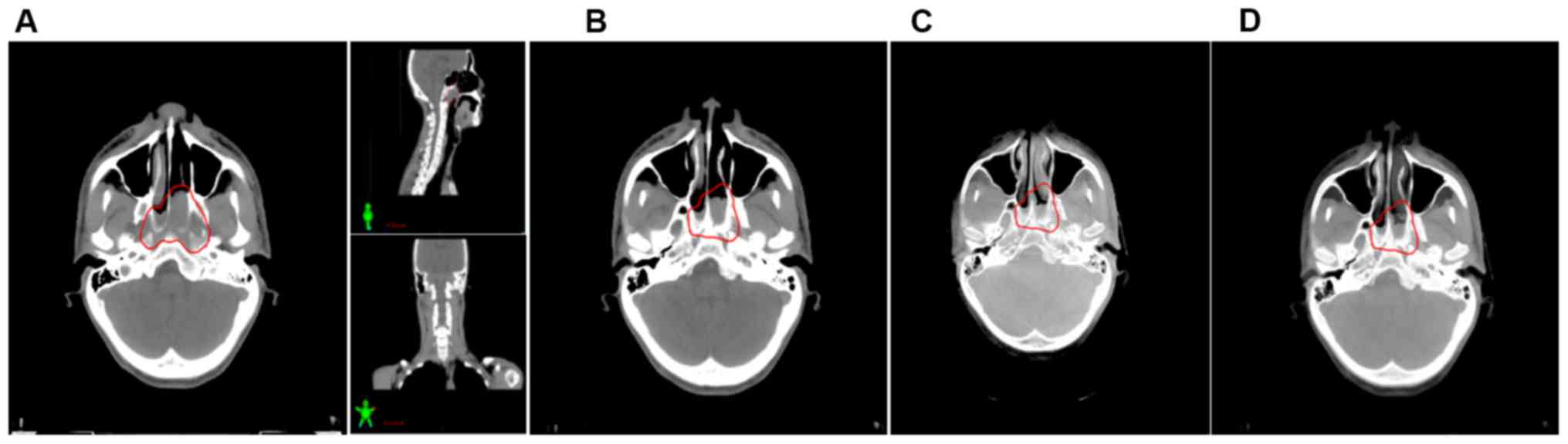
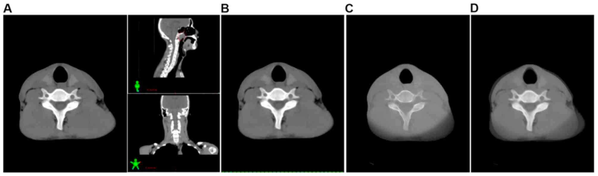
In total, 4,613 position verification scans were
performed and analyzed. A comparison was made between these
acquired images and the corresponding planning CT scan images to
determine the positional shifts and ultimately measure the shifts
of the bony reference regions in the AP, SI and RL directions
(Figs. 1–3; representative images from one patient).
The planning CT image was used as the control for each patient.
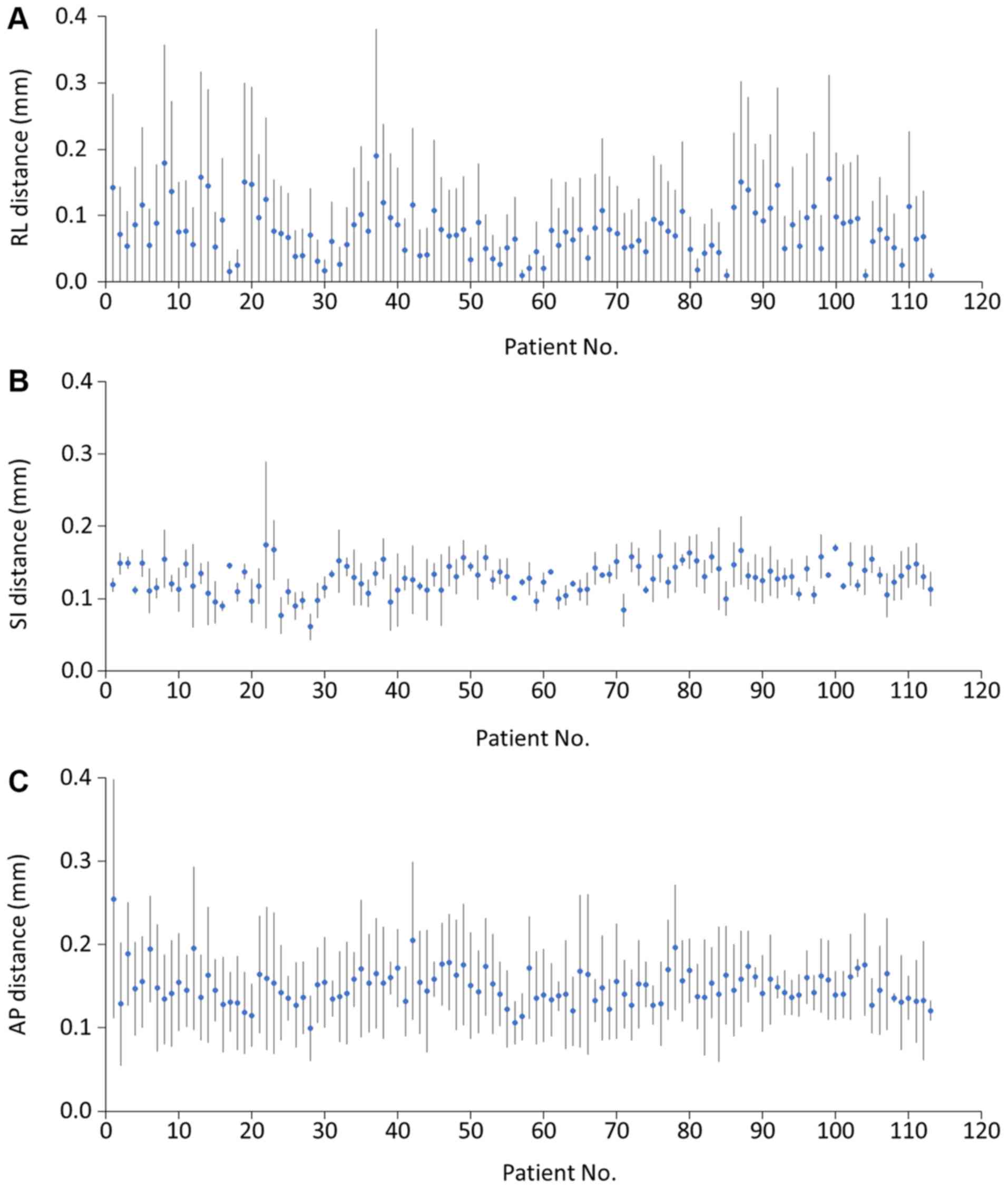
To evaluate the setup errors, the ROI positional
shifts were measured weekly, with each patient having at least
three scans during the RT course. The results revealed that
deviation in the head was in the range of 0–4 mm in the AP
direction, 0–3 mm in the RL direction and 0–2 mm in the SI
direction. The prevalence of errors >2 mm were 7 (2.1%) in the
AP direction. In the upper neck, the range of deviations were 0–2,
0–3 and 0–2 mm in the RL, SI and AP directions, respectively. The
frequencies of errors >2 mm were 5 (1.5%) in the SI direction.
Bony reference deviation in the lower neck was in the range of 0–5
mm in the RL direction, 0–2 mm in the SI direction and 0–3 mm in
the AP direction (Fig. 4). The
incidence of errors >2 mm in the RL, SI and AP directions were
62 (18.3%) in the RL direction, 0 in the SI direction and 2 (0.6%)
in the AP direction (Table
III).
| Table III.Translation shifts of >2 mm in RL,
SI and AP directions of head, upper neck, and lower neck. |
Table III.
Translation shifts of >2 mm in RL,
SI and AP directions of head, upper neck, and lower neck.
|
| Interfraction >2
mm, n (%) |
|---|
|
|
|
|---|
| Region | RL | SI | AP |
|---|
| Head | 1 (0.2) | 0 (0.0) | 7 (2.1) |
| Upper neck | 0 (0.0) | 5 (1.5) | 0 (0.0) |
| Lower neck | 62 (18.3) | 0 (0.0) | 2 (0.6) |
Calculations to estimate the group systematic and
random errors were conducted using the Stroom definition of error
estimation (13). The results for
group systematic and random errors were 0.509 and 0.208 mm in the
RL direction, respectively; in the SI direction they were 0.227 and
0.160 mm for group systematic errors and random errors,
respectively; and the group systematic and random errors in the AP
direction were 0.755 and 0.345 mm, respectively (Table IV).
| Table IV.Summary of interfraction
translational error in each dimension. |
Table IV.
Summary of interfraction
translational error in each dimension.
| Parameter | Right-left |
Superior-inferior |
Anterior-posterior |
|---|
| Mean, mm | 1.494 | 1.279 | 1.898 |
| SD, mm | 0.217 | 0.215 | 0.427 |
| Minimum, mm | 0.000 | 0.000 | 0.000 |
| Maximum, mm | 9.000 | 8.000 | 14.000 |
| ∑ | 0.509 | 0.227 | 0.755 |
| σ | 0.208 | 0.160 | 0.345 |
| MPTV, mm | 1.418 | 0.566 | 2.129 |
AP direction possesses the highest
MPTV following CBCT evaluation
Based on the van-Herk formula (MPTV=2.5Σ+0.7σ), the
ideal MPTVs were derived from the setup errors. With the aim to
accurately deliver radiation doses to the targets and the
associated surrounding normal tissues, the margins required in the
different directions were 1.418, 0.566 and 2.129 mm in the RL, SI
and AP directions, respectively (Table
IV). When a comparison was made amongst the three anatomical
levels there was an increase in the MPTVs from the cranial to the
caudal region. With regard to different anatomic levels, the
overall calculated MPTVs were the greatest in the lower neck (2 mm)
followed by the upper neck region (1.4 mm). At the head level, the
calculated margin was 0.9 mm, as presented in Table V.
| Table V.Reported planning target volume
margins from the present and previous studies. |
Table V.
Reported planning target volume
margins from the present and previous studies.
| Study (Author,
year) | Imaging | Correction
protocol | Margin range,
mm | Error margins,
mm | (Refs.) |
|---|
| Present study | CBCT | Weekly | Head | 0.90 |
|
|
|
|
| Upper neck | 1.40 |
|
|
|
|
| Lower neck | 2.00 |
|
|
| CBCT |
| Overall | 1.42 (RL) |
|
|
|
|
|
| 0.57 (SI) |
|
|
|
|
|
| 2.13 (AP) |
|
| Su et al,
2015 | Orthogonal kV
image | None | Skull (clivus) | 3.20–4.40 | (12) |
|
|
|
| C3 spine | 4.40–5.50 |
|
|
|
|
| C6 spine | 4.40–6.90 |
|
| Cheo et al,
2015 | CBCT | No | Skull (clivus) | 1.75–2.33 | (19) |
|
|
|
| C4 spine | 2.61–4.33 |
|
|
|
|
| C7 spine | 2.72–6.52 |
|
|
|
| Weekly | Skull (clivus) | 0.15–1.20 |
|
|
|
|
| C4 spine | 0.97–3.72 |
|
|
|
|
| C7 spine | 1.20–6.08 |
|
|
| CBCT | Weekly | Overall | 3.00 (RL) |
|
|
|
|
|
| 1.30 (SI) |
|
|
|
|
|
| 2.60 (SI) |
|
| van Kranen et
al, 2009 | CBCT | SAL | Skull
(Occiput) | 4.60–7.00 | (20) |
|
|
|
| C1-c3 spine | 3.80–4.70 |
|
|
|
|
| C5-c7 | 5.40–6.00 |
|
| Djordjevic et
al, 2014 | Orthogonal kV
image | No | Skull
(maxilla) | 5.20–5.90 | (21) |
|
|
|
| C2 spine | 4.50 (SI), 6.50
(AP) |
|
|
|
|
| C5 spine | 5.00–9.30 |
|
|
|
| Daily | Skull
(maxilla) | 4.20–5.90 |
|
|
|
|
| C2 spine | 2.30 (SI), 2.60
(AP) |
|
|
|
|
| C5 spine | 2.60–5.00 |
|
| Wang et al,
2009 | CBCT | None | Overall | 0.70 | (25) |
|
|
|
|
| −0.70 |
|
|
|
|
|
| 0.30 |
|
| Mongioj et
al, 2011 | CT | None | Overall | 3.40 (RL) | (26) |
|
|
|
|
| 3.00 (SI) |
|
|
|
|
|
| 3.20 (AP) |
|
| Dionisi et
al, 2012 | CBCT | None | Overall | 3.48 (RL) | (27) |
|
|
|
|
| 4.08 (SI) |
|
|
|
|
|
| 4.33 (AP) |
|
| Kapanen et
al, 2013 | Orthogonal kV
image | Weekly | Skull
(occiput) | 6.10 (SI), 8.30
(AP) | (28) |
|
|
|
| C1-c2 spine | 4.80–7.00 |
|
|
|
|
| C5-c7 | 4.90–5.70 |
|
| Anjanappa et
al, 2017 | kV images | None | Clivus | 4.40 (SI), 4.00
(AP), 3.20 (RL) | (29) |
|
|
|
| C3 | 5.50 (SI), 5.00
(AP), 4.40 (RL) |
|
|
|
|
| C6 | 6.40 (SI), 4.40
(AP), 6.90 (RL) |
|
Setup errors of the different levels
following ANOVA
To establish if there were any statistical
differences amongst the measured setup errors in the various
regions, bony landmarks were used to represent the different
regions: The nasal septum and pterygoid process represented the
head; the upper neck was represented by cervical vertebrae 1–3; and
the lower neck was denoted by cervical vertebrae 4–6. One-way ANOVA
was performed to compare the setup errors in the different levels
(upper neck, lower neck and head) and different directions (RL, SI
and AP). Significant differences were observed among the different
directions and the different levels (Table VI). The results demonstrated that
the setup errors in all of the directions were significantly
different when comparing the NPC levels of interest (P<0.01).
Within each direction, the RL and AP directions had the greatest
number of setup errors in the lower neck region, while the SI
direction had the greatest number of setup errors in the upper neck
region.
| Table VI.Analysis of variance of setup errors
in different regions in RL, SI and AP directions. |
Table VI.
Analysis of variance of setup errors
in different regions in RL, SI and AP directions.
| Direction | Head | Upper neck | Lower neck | F-value | P-value |
|---|
| RL, mm | 1.20±0.013 | 1.30±0.009 | 2.00±0.013 | 187.55 | <0.01 |
| SI, mm | 1.14±0.007 | 1.40±0.011 | 1.30±0.008 | 24.58 | <0.01 |
| AP, mm | 1.23±0.020 | 1.95±0.030 | 2.51±0.060 | 117.22 | <0.01 |
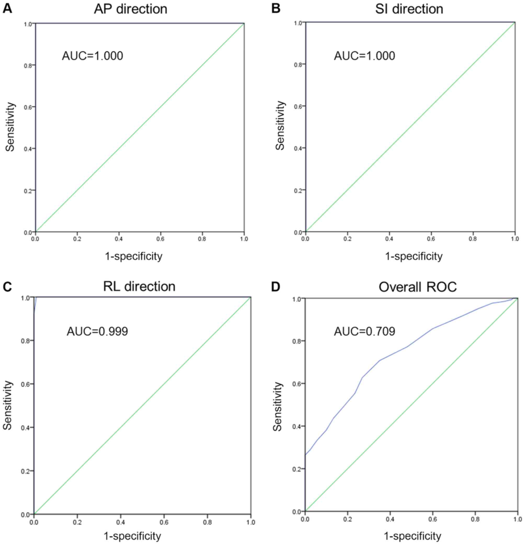
ROC curves
To evaluate the sensitivity and specificity of the
CBCT examinations, ROC curve analysis of each direction and overall
ROC analysis of the three directions were performed. The overall
ROC analysis was comprised of all of the data, regardless of the
direction. These values assisted in describing the abilities of the
CBCT to correctly give a value where a setup error existed and to
correctly rule out the absence of a setup shift depending on the
set shift cut-off values. To achieve this goal, individual
systematic errors were compared with the calculated MPTV values.
The essential part of the curve is the area under the curve. For
the AP, SI and RL directions respectively, the ROC analysis
revealed perfect sensitivity in each direction (Fig. 5A-C). For the combined ROC curve
analysis, there was an area of 0.709, which indicates fair levels
of accuracy (Fig. 5D). Thus, the
CBCT examination was able to correct the setup errors and thereby
contribute to accurate RT.
Discussion
The distribution of radiation doses of IMRT in NPC
cases is solely based on the volume of data from planning CT scans;
however, these images only provide the anatomical structures of the
patient at that particular time without considering the daily
changes in patients with regard to target volumes, OARs and the
anatomic position (15). The
existence of steep dose gradients between the structures may imply
that lower doses reach the primary tumor and the surrounding normal
tissues receive an overdose. Setup errors have a great effect on
IMRT due to its sharp dose gradient. In situations where setup
errors exist, a tiny deviation in the isodose shift may
significantly lower the dose in the target volume and increase the
doses administered to the OARs during the whole course of the IMRT
treatment. When the target region receives a reduced radiation
dose, this can lead to local tumor recurrence, over-irradiation of
normal tissues, which causes unnecessary toxicity, and it can
ultimately increase the probability of further complications. Tumor
regression coupled with changes that occur in the target position
and anatomical structures leads to the reduction of treatment
accuracy during the total course of RT. In addition, errors can
occur at the localization, planning or delivery stages of the
treatment (12).
Rigid immobilization and frequent treatment portal
verification form an important part of image-guided RT (IGRT). A
number of institutions that offer head and neck tumor treatment
employ uniform MPTVs of 3–5 mm with applicable image guidance
protocols to account for setup errors during the course of the
treatment (16). A comprehensive
review focusing on setup verification through the use of portal
imaging by Hurkmans et al (17) concluded that an SD of ≤2 mm for
random and systematic setup errors can be considered as ‘state of
the art’ when using the currently available positioning equipment.
Even though efficient head and neck immobilization can be achieved,
a certain degree of movement at the neck and skull level still
exists. Zhang et al (18)
investigated the use of a CT-on-rails system and concluded that in
the day to day setup error measurements at different levels, the
greatest shift was recorded in the lower neck (C6 level). In their
study of 14 patients, the differences amongst the levels were in
the range of 2–3 mm, suggesting that there was variability in the
setup uncertainties in the different levels of the head and neck.
With this in mind, it is therefore necessary to consider the
relative positional variations when performing setup corrections or
implementing treatment margins. In addition, a uniform margin may
not be ideal at all of the levels of the head and neck treatments.
This challenge in the differences in margins can be solved through
the formulation of reasonable and sufficient margins or through the
utilization of more advanced technology that yields reduced setup
errors.
Several studies have investigated setup errors in
the various sub-regions of the head and neck (12,19,20). In
all of these studies, planning CT images were matched with the CBCT
views. In the present study, the errors were evaluated in three
sites, namely the upper neck, lower neck and head. The head, which
was represented by the nasal septum and pterygoid process, is an
important region in NPC RT as there are critical structures in
close proximity to the optic apparatus and brainstem. This bony
reference point matching provides a close approximation of the
target and OAR match. A previous study has also focused on the
occiput, maxilla and mandible (21).
The bony reference point was a novel approach to determine if there
were any differences between the earlier studies and the present
study.
The mandible produces different setup errors as it
moves independently of the skull if it was employed for matching
(21). The organs of interest in the
present study were those associated with NPC, thus errors in the
mandible were not measured. The upper neck (cervical vertebrae 1–3)
region represents a region were the levels II and III neck lymph
nodes are located. The C4-C6 region, which represents the lower
neck, corresponds to the lower lymph node region.
Cheo et al (19) demonstrated that the setup errors were
small in the head region when in comparison with the neck, and the
errors were primarily located in the RL direction in the neck. In
the present study, the largest setup error was noted in the lower
neck AP direction.
van Kranen et al (20) also investigated the setup errors in
eight different levels of the head and neck using regular CBCT
scans. The results revealed that the systematic errors ranged
between 1.1 and 3.4 mm, whilst the random errors were observed to
be 1.3–2.5 mm in 38 cases. Their results were also suggestive of a
greater incidence of errors in the lateral and AP directions of the
lower neck. This was in keeping with the results reported by Polat
et al (22), which suggested
that local setup errors were large and thus, the current PTV may
not be enough to account for these setup uncertainties. In light of
this, it was suggested that in order to drive correction protocols
and to reduce the impact of local setup variations, multiple ROI
registrations should be performed.
A study by Djordjevic et al (21) in evaluating different correction
protocols revealed that the setup errors were more prevalent in the
lower neck. The systematic error ranged between 0.9 and 2.3 mm and
the random errors ranged between 1.1 and 1.6 mm, with the maximum
number of recordings observed at the C6 level.
In a study by Ove et al (23) involving the use of rail CT to confirm
position verification, the lower neck was displaced anteriorly by
3.08±0.17 mm, and no systematic lateral or craniocaudal shifts were
noted. In the RL, SI and AP directions in the lower neck, the SDs
of the random errors were 3.3, 2.6 and 3.9 mm, respectively. These
results illustrated that the lower neck region exceeded the
planning margins. A systematic anterior displacement was observed
in the lower neck and the random errors exceeded the limits.
Therefore, a larger planning boundary should be employed in the
neck region. Su et al (12)
conducted weekly kV CBCT-guided IMRT in 30 NPC cases. Their PTV
margins were 3.0, 1.3 and 2.6 mm in the RL, SI and AP directions,
respectively. They concluded that the setup errors of the neck
region were larger than those in the head during RT.
The discrepancy of the lower neck errors being
larger than those in the head can be explained by the following: i)
Patients with NPC with oral mucositis during the course of RT tend
to have a lowered appetite, resulting in weight loss, and
ultimately the neck becomes thinner; ii) as the large neck lymph
shrinks during the treatment period, the diameter of the neck is
reduced significantly; iii) as a result, the mask becomes loose,
which then allows the neck to move laterally; and iv) during the
late phases of the RT course there will be a different degree of
radioactive dermatitis in the neck due to pain, and the patient
will automatically move their body and shift position (12).
The setup error difference in the head and neck is
of clinical importance due to the following: i) IGRT with IMRT
monitors the patient's physical changes daily or weekly, if errors
are detected corrections can be made early; ii) the neck region is
more flexible in comparison to the head, hence it is necessary to
better immobilize it in order to keep head and neck setup errors to
a minimum (24); iii) detection of
changes in contours due to shrinking cervical lymph nodes will
allow for the modification of the ROIs and therefore alter the
treatment plan in order to lower the radiation dose in the spinal
cord and skin; iv) during the treatment course, active prevention
and control of oral mucositis should be considered and the patients
with NPC should be encouraged to eat or have enteral nutrition in
order to maintain body weight; and v) radioactive dermatitis should
not be overlooked (12). In cases of
severe lesions, the therapy sessions can be deferred to a later
stage. Head and neck motion that arises due to discomfort should be
kept to a minimum. Each RT unit ought to establish the CTV-to-MPTV
according to the situation. Differentiating the head and neck
allows for accurate boundaries to be established for RT patients
(12).
In the present study, kV CBCT-guided IMRT was
utilized in 113 NPC cases. The CBCT scan images were matched to the
planning CT images to establish the different setup errors in the
upper neck, lower neck and head. Comparisons were then performed
for the three levels, in the RL, AP and SI directions. As there are
reports on the local setup error variations that exceed overall
patient setup uncertainty in head and neck carcinoma, the present
study performed registration at multiple ROIs to allow for the
proper evaluation of the actual PTV margins. Currently, to the best
of our knowledge, there have been no studies on CBCT utilization in
IMRT that have made judgments based on ROC analysis to determine
the specificity of the diagnostic tool. The analysis performed in
the present study demonstrates a good test, but not a definitive
one.
The results of the present study revealed that a PTV
margin of 1.5, 0.6 and 2.2 mm in the RL, SI and AP directions,
respectively, is recommended for the CBCT image registrations used.
For the head, and upper and lower neck the MPTVs were 0.9, 1 4 and
2 mm, respectively. The differences in the error limit can be
explained by the increased frequency of scans that were performed
in the current study compared with previous studies. A literature
search revealed that the majority of the previous studies on this
topic did not include >80 patients, whereas the present study
included data from >100 patients (12,21,24).
Setup errors exist in the RL, SI and AP directions
in NPC under IMRT in the present study. The lower neck region has
higher setup errors when compared with the upper neck and head
region during RT. At Nanfang hospital the recommended MPTVs are 1.5
mm in the RL direction, 0.6 mm in the SI direction and 2.2 mm in
the AP direction for patients undergoing IMRT with weekly CBCT
scans. Frequent imaging with CBCT to verify the target volume is of
importance in order to maintain the accurate delivery of radiation.
Derived target margins, if applied, will avoid the possibility of
target under-dosage. CBCT may largely improve the accuracy of RT by
minimizing the setup errors and MPTV. The ROC plot indicated that
CBCT may be a fair tool for detecting setup errors in the present
study.
One limitation of the present study was that it did
not account for residual errors, as a second (verification) CBCT
scan following repositioning was not performed. In other studies
(25–29), for the prostate bed, and head and
neck, the residual errors were determined by performing a second
CBCT following treatment and matching it with the planning CT. Of
course, this procedure will also lead to a higher dose exposure to
the patient. The assessment of the residual errors will allow for
calculating CTV-to-PTV expansion margins when image guidance is
used, which should in general be smaller than the values obtained
in the present study. As the safety margins are usually applied in
three dimensions, even a small reduction can result in a
considerably reduced normal tissue volume (30). The patient weight loss during the
course of treatment associated with setup errors was not analyzed
even though it contributes to setup errors. In addition, daily CBCT
scans were not performed for every case included in the present
study due to patient economic status and other hospital resource
constraints. Noise, which is a pixel variation associated with the
stochastic nature of radiation is another bias. Quantifying noise
will involve detecting failures in the execution of the x-ray
device in this case the CBCT scanner, by doing a comparison of the
values measured and baseline performance. Noise is understood to
compromise the visibility of relevant structures of anatomy.
In conclusion, CBCT was demonstrated to greatly
improve the accuracy of radiotherapy by minimizing the setup errors
and MPTV. It was also revealed that setup errors are more prevalent
in the lower neck for head and neck CBCT.
Acknowledgements
Not applicable.
Funding
The study described in this paper was substantially
supported by a grant from the National Natural Science Foundation
of China (grant no. 81772914; http://www.nsfc.gov.cn/) and a grant from Guangdong
Provincial Department of Science and Technology (grant No.
2016A030313738; http://www.gdstc.gov.cn/).
Availability of data and materials
The datasets used and/or analyzed during the current
study are available from the corresponding author on reasonable
request.
Authors' contributions
KML, ZD and LZ conceived and designed the study. JL
collected the data. KML and LZ analysed and interpreted the data.
KML, ZD and LZ wrote the paper. JL, KML, ZD and LZ reviewed and
edited the manuscript.
Ethics approval and consent to
participate
All procedures performed in this study were in
accordance with the ethical standards of the institutional (Nanfang
Hospital Review Board) and national research committee and with the
1964 Helsinki declaration and its later amendments. The review
board approved the study. Written informed consent was obtained
from all individual participants included in the study.
Patient consent for publication
Informed consent was obtained from all participants
to perform the study and to publish the findings.
Competing interests
The authors declare that they have no competing
interests.
References
|
1
|
Chua MLK, Wee JTS, Hui EP and Chan ATC:
Nasopharyngeal carcinoma. Lancet. 387:1012–1024. 2016. View Article : Google Scholar : PubMed/NCBI
|
|
2
|
Lo KW, Chung GT and To KF: Deciphering the
molecular genetic basis of NPC through molecular, cytogenetic, and
epigenetic approaches. Semin Cancer Biol. 22:79–86. 2012.
View Article : Google Scholar : PubMed/NCBI
|
|
3
|
Zhong H and Chen G, Lin D and Chen G:
Comparison of side effects of intensity modulated radiotherapy and
conventional radiotherapy in 69 cases with nasopharyngeal
carcinoma. Lin Chung Er Bi Yan Hou Tou Jing Wai Ke Za Zhi.
27:462–464. 2013.(In Chinese). PubMed/NCBI
|
|
4
|
Han C, Chen YJ, Liu A, Schultheiss TE and
Wong JY: Actual dose variation of parotid glands and spinal cord
for nasopharyngeal cancer patients during radiotherapy. Int J
Radiat Oncol Biol Phys. 70:1256–1262. 2008. View Article : Google Scholar : PubMed/NCBI
|
|
5
|
Zhang X, Li M, Cao J, Luo JW, Xu GZ, Gao
L, Yi J, Huang X, Xiao J, Li S and Dai J: Dosimetric variations of
target volumes and organs at risk in nasopharyngeal carcinoma
intensity-modulated radiotherapy. Br J Radiol. 85:e506–e513. 2012.
View Article : Google Scholar : PubMed/NCBI
|
|
6
|
Boda-Heggemann J, Lohr F, Wenz F, Flentje
M and Guckenberger M: kV cone-beam CT-based IGRT: A clinical
review. Strahlenther Onkol. 187:284–291. 2011. View Article : Google Scholar : PubMed/NCBI
|
|
7
|
Chau RM, Teo PM, Kam MK, Leung SF, Cheung
KY and Chan AT: Dosimetric comparison between 2-dimensional
radiation therapy and intensity modulated radiation therapy in
treatment of advanced T-stage nasopharyngeal carcinoma: To treat
less or more in the planning organ-at-risk volume of the brainstem
and spinal cord. Med Dosim. 32:263–270. 2007. View Article : Google Scholar : PubMed/NCBI
|
|
8
|
van Herk M, Remeijer P, Rasch C and
Lebesque JV: The probability of correct target dosage:
Dose-population histograms for deriving treatment margins in
radiotherapy. Int J Radiat Oncol Biol Phys. 47:1121–1135. 2000.
View Article : Google Scholar : PubMed/NCBI
|
|
9
|
Wilkinson JM: Geometric uncertainties in
radiotherapy. Br J Radiol. 77:86–87. 2004. View Article : Google Scholar : PubMed/NCBI
|
|
10
|
Chinese committee for staging of
nasopharyngeal carcinoma report on revision of the Chinese 1992
staging system for nasopharyngeal carcinoma. Radiation Oncol.
2:233–240. 2013. View Article : Google Scholar
|
|
11
|
DICOM, . Scope and Field of Application.
http://dicom.nema.org/medical/dicom/current/output/chtml/part01/chapter_1.htmlJune
12–2017
|
|
12
|
Su J, Chen W, Yang H, Hong J, Zhang Z,
Yang G, Li L and Wei R: Different setup errors assessed by weekly
cone-beam computed tomography on different registration in
nasopharyngeal carcinoma treated with intensity-modulated radiation
therapy. OncoTargets and Ther. 8:2545–2553. 2015.
|
|
13
|
Stroom JC and Heijmen BJ: Geometrical
uncertainties, radiotherapy planning margins, and the ICRU-62
report. Radiother Oncol. 64:75–83. 2002. View Article : Google Scholar : PubMed/NCBI
|
|
14
|
Zweig MH and Campbell G:
Receiver-operating characteristic (ROC) plots: A fundamental
evaluation tool in clinical medicine. Clin Chem. 39:561–577.
1993.PubMed/NCBI
|
|
15
|
Tan W, Li Y, Han G, Xu J, Wang X, Li Y and
Hu D: Target volume and position variations during
intensity-modulated radiotherapy for patients with nasopharyngeal
carcinoma. Onco Targets Ther. 6:1719–1728. 2013. View Article : Google Scholar : PubMed/NCBI
|
|
16
|
Chen AM, Farwell DG, Luu Q, Donald PJ,
Perks J and Purdy JA: Evaluation of the planning target volume in
the treatment of head and neck cancer with intensity-modulated
radiotherapy: What is the appropriate expansion margin in the
setting of daily image guidance? Int J Radiat Oncol Biol Phys.
81:943–949. 2011. View Article : Google Scholar : PubMed/NCBI
|
|
17
|
Hurkmans CW, Remeijer P, Lebesque JV and
Mijnheer BJ: Set-up verification using portal imaging; review of
current clinical practice. Radiother Oncol. 58:105–120. 2001.
View Article : Google Scholar : PubMed/NCBI
|
|
18
|
Zhang L, Garden AS, Lo J, Ang KK, Ahamad
A, Morrison WH, Rosenthal DI, Chambers MS, Zhu XR, Mohan R and Dong
L: Multiple regions-of-interest analysis of setup uncertainties for
head-and-neck cancer radiotherapy. Int J Radiat Oncol Biol Phys.
64:1559–1569. 2006. View Article : Google Scholar : PubMed/NCBI
|
|
19
|
Cheo T, Loh Y, Chen D, Lee KM and Tham I:
Measuring radiotherapy setup errors at multiple neck levels in
nasopharyngeal cancer (NPC): A case for differential PTV expansion.
Radiother Oncol. 117:419–424. 2015. View Article : Google Scholar : PubMed/NCBI
|
|
20
|
van Kranen S, van Beek S, Rasch C, van
Herk M and Sonke JJ: Setup uncertainties of anatomical sub-regions
in head-and-neck cancer patients after offline CBCT guidance. Int J
Radiat Oncol Biol Phys. 73:1566–1573. 2009. View Article : Google Scholar : PubMed/NCBI
|
|
21
|
Djordjevic M, Sjöholm E, Tullgren O and
Sorcini B: Assessment of residual setup errors for anatomical
sub-structures in image-guided head-and-neck cancer radiotherapy.
Acta Oncol. 53:646–653. 2014. View Article : Google Scholar : PubMed/NCBI
|
|
22
|
Polat B, Wilbert J, Baier K, Flentje M and
Guckenberger M: Nonrigid patient setup errors in the head-and-neck
region. Strahlenther Onkol. 183:506–511. 2007. View Article : Google Scholar : PubMed/NCBI
|
|
23
|
Ove R, Cavalieri R, Noble D and Russo SM:
Variation of neck position with image-guided radiotherapy for head
and neck cancer. Am J Clin Oncol. 35:1–5. 2012. View Article : Google Scholar : PubMed/NCBI
|
|
24
|
Li H, Zhu XR, Zhang L, Dong L, Tung S,
Ahamad A, Chao KS, Morrison WH, Rosenthal DI, Schwartz DL, et al:
Comparison of 2D radiographic images and 3D cone beam computed
tomography for positioning head-and-neck radiotherapy patients. Int
J Radiat Oncol Biol Phys. 71:916–925. 2008. View Article : Google Scholar : PubMed/NCBI
|
|
25
|
Wang J, Bai S, Chen N, Xu F, Jiang X, Li
Y, Xu Q, Shen Y, Zhang H, Gong Y, et al: The clinical feasibility
and effect of online cone beam computer tomography-guided
intensity-modulated radiotherapy for nasopharyngeal cancer.
Radiother Oncol. 90:221–227. 2009. View Article : Google Scholar : PubMed/NCBI
|
|
26
|
Mongioj V, Orlandi E, Palazzi M, Deponti
E, Marzia F, Stucchi C, Sangalli C, Fallai C, Zonca G, Olmi P and
Pignoli E: Set-up errors analyses in IMRT treatments for
nasopharyngeal carcinoma to evaluate time trends, PTV and PRV
margins. Acta Oncol. 50:61–71. 2011. View Article : Google Scholar : PubMed/NCBI
|
|
27
|
Dionisi F, Palazzi MF, Bracco F, Brambilla
MG, Carbonini C, Asnaghi DD, Monti AF and Torresin A: Set-up errors
and planning target volume margins in head and neck cancer
radiotherapy: A clinical study of image guidance with on-line
cone-beam computed tomography. Int J Clin Oncol. 18:418–427. 2013.
View Article : Google Scholar : PubMed/NCBI
|
|
28
|
Kapanen M, Laaksomaa M, Tulijoki T,
Peltola S, Wigren T, Hyodynmaa S and Kellokumpu-Lehtinen PL:
Estimation of adequate setup margins and threshold for position
errors requiring immediate attention in head and neck cancer
radiotherapy based on 2D image guidance. Radiat Oncol. 8:2122013.
View Article : Google Scholar : PubMed/NCBI
|
|
29
|
Anjanappa M, Rafi M, Bhasi S, Kumar R,
Thommachan KC, Bhattacharya T and Ramadas K: Setup uncertainties
and PTV margins at different anatomical levels in intensity
modulated radiotherapy for nasopharyngeal cancer. Rep Pract Oncol
Radiother. 22:396–401. 2017. View Article : Google Scholar : PubMed/NCBI
|
|
30
|
Kron T: Reduction of margins in external
beam radiotherapy. J Med Phys. 33:41–42. 2008. View Article : Google Scholar : PubMed/NCBI
|