Introduction
Finite element analysis (FEA) utilizes numerical
analysis and minimizes variational calculus to approximate
mathematical and physical problems. Turner et al (1) proposed the basic theory of FEA in
1956. FEA has since been refined to a high level of precision due
to the decline in cost and increase in computing power resulting
from rapid technological development. Belytschko et al
(2) were the first to apply this
technique to understand the mechanical behavior of the human spinal
column. The application of FEA in biomechanics has accomplished
considerable progress and has been widely used in orthopedics,
dentistry and cerebrovascular diseases as an essential,
complementary and effective alternative for in vitro
studies. Models based on computed tomography (CT) imaging
accurately visualize the geometric information of real human
tissues and provide a reliable approach for the biomechanical
analysis of bone tissues. Traditional model construction methods
manually discern and draft the contour of the bone tissue on the
basis of geometrical shape and size, using the initial scanned
sample to construct a model appropriate for FEA study (3). The approach of these methods is
simple and intuitive. However, discriminating and defining complex
and subtle structures under pathological conditions is difficult.
For example, performing 3D reconstruction in elderly patients with
osteoporosis and degenerative osteophytes is challenging since
similar gray and CT values discriminate the margin between the bone
and soft tissues, which are ambiguous to the naked eye.
Nevertheless, discriminating tissue margins in elderly patients is
not difficult when the appropriate computer software is used. At
the beginning of the 21st century, the development of CT imaging
technology, along with FEA, has benefited from advances in computer
power and CT-based modeling has a variety of new medical
applications (4–14).
The present study introduces a 3D modeling method
that applies 3D processing and modeling techniques. In this method,
the margins of various tissues are differentiated automatically by
software that analyzes data according to the intrinsic gray value
of each tissue. The analysis results and the CT imaging data are
then converted into the DICOM file format, which preserves all
tissue density information. Assignment of Young’s modulus to
non-uniform tissue, which is based on the empirical expressions of
the correlations among density, CT value and Young’s modulus,
becomes possible at this stage, particularly in bone tissues. The
data is readily transferrable into other medical image processing
software, including Mimics (Materialise, Leuven, Belgium) or
Simpleware (Simpleware Ltd., Exeter, UK).
A new approach of model construction is proposed.
The method implements automatic 3D tissue discrimination and
incisions using the Siemens syngo® 3D Workplace
(Siemens, Munich, Germany) prior to transferring the data to
Mimics. Converting CT images to a 3D model is fast, thus allowing
more time for conducting FEA. The new model significantly improves
analysis efficiency and research management. A preliminary fracture
risk-evaluation study was performed in elderly individuals,
according to FEA results on the basis of the new 3D modeling
method.
Materials and method
Case selection
A total of 9,670 lumbar CT examination cases were
provided by Jilin University (Changchun, China) between January
2008 and June 2011. The enrollment criterion was restricted to
degenerative lumbar disease, excluding patients with lumbar
fractures and tumors. This study was conducted in accordance with
the Declaration of Helsinki and with approval from the Ethics
Committee of Jilin University. Written informed consent was
obtained from all participants.
CT scan parameters
Patients were examined by 64-slice spiral CT
(Siemens). The scan ranged between thoracic vertebra 11 and sacrum
1 using the following CT scan parameters: Tube voltage, 120 kV;
effective tube current, 60 mV; and reconstruction thickness, 0.6
mm. Data were recorded in the DICOM format.
Model construction by the conventional
Mimics method
One individual in the 20–40-year-old age group was
randomly selected for the preliminary step of the study. First, a
model of the lumbar spine of this individual was constructed using
conventional Mimics software. This case was prepared for the
innovative model construction method in the next step. The average
height of each vertebra (~3 cm) was divided into ~50 consecutive CT
imaging slices. The conventional finite element model was
constructed by discerning the margin of the bone tissue and by
manually cutting the soft tissue slice-by-slice.
Image processing via innovative 3D
modeling method
Raw DICOM data of the lumbar spine of the patient
underwent tissue marking, 3D cutting, home-positioning and
multi-planar reconstruction using syngo software on the Siemens
Workstation.
Tissue marking
Raw DICOM data were transferred to the Siemens syngo
CT Workstation. Slices of 1.0-mm sequence were dragged into the 3D
application and the sagittal frame was activated in the ‘bone
removal’ mode. Region selection, was the first step, where a
default threshold of 175 HU in the body mode was selected to ensure
that pixels with a CT value >175 HU showed blue markings.
Secondly, the image was refined. The segmentation strength value at
this stage was 50 and the noise tolerance was 600 HU. Refinement
was conducted by recalling bone tissue that had been neglected by
the software. Finally, rendering of the marking was completed and
saved to ensure that a browser list of 3D applications remained on
the workstation to allow for the extraction of DICOM data with
processed tissue markings in the future.
3D incision
After tissue marking, the sagittal frame of the
‘bone display’ item was selected in the ‘bone removal’ mode. Next,
the ‘Osseous Transparent metal VP’ of the visual reaction time in
the type work list was selected. The 3D transparent display of the
lumbar spine bone structure facilitated the 3D incision of the
lumbar spine. The lumbar vertebra was incised using the 3D incision
tools of the syngo software and then rotated 360° in the 3D
transparent mode. This action constituted the only step for normal
lumbar vertebra incision and did not necessitate a slice-by-slice
drafting of the contour in Mimics. The ‘Osseous Shaded VP’ mode was
used to recall bone tissue with low density, which had not been
shown clearly in the ‘Osseous Transparent metal VP’ mode. The
aforementioned steps allowed for high-efficiency extraction of the
exact morphology of the lumbar vertebra structure.
3D orientation
The single incised lumbar vertebra was restored into
its original sagittal orientation following selection of ‘the left
to right’ item in oriental mode. The lumbar vertebra was further
restored into its original 3D orientation following the selection
of ‘home zoom/pan’ item in the oriental mode. Proper restoration of
3D vertebrae orientation after 3D incision was a critical step for
achieving exact 3D matching of each data pixel with the raw DICOM
data. The resulting orientations were then processed along the x, y
and z axes.
Multi-plane reconstruction
‘Parallel ranges’ in the setting mode was selected
following a 3D incision to obtain a multi-plane reconstruction of a
single lumbar vertebra. The reconstructed multi-plane horizontal
slices, with 1.0 mm thickness and 1.0 mm interval, were arranged
from the superior to the inferior section of the vertebra. Bone
tissue data was saved in DICOM format after processing.
Data transfer from syngo to Mimics and
further processing
DICOM data of each vertebra were imported into
Mimics for further processing. Only the data of one vertebral body
were left in Mimics since the soft tissue and other vertebral
bodies were eliminated during processing with the Siemens syngo 3D
CT Workplace. All bone tissue information of the selected vertebra
was obtained following the removal of the surrounding soft tissue
by adjusting the threshold of the gray value to the minimum.
Polishing and remeshing
The model was meshed and smoothed using Magics
software included in the Mimics software. It was then remeshed
using the split-based method. Minimum and maximum edge lengths of
the tetrahedral elements were set at 0.7 and 0.9 mm,
respectively.
Congruence between the models constructed
by traditional and innovative 3D modeling methods
Two models were constructed with the same raw DICOM
data of a single vertebra to compare the congruence between the
traditional and innovative methods. The two models were then
transferred into the Mimics software using the same coordinates to
form a merged image.
Time consumption of the traditional and
innovative 3D modeling methods
The 9,670 lumbar CT examinations in our
institution’s database were divided into the following five age
groups: 20–40, 41–50, 51–60, 61–70 and >70 years old. Five cases
were selected randomly from each age group and models of the entire
lumbar spine (L1–5) were constructed from each patient. Traditional
and innovative methods were used, creating 10 models in total. Time
consumption of each model was recorded and statistical analysis was
performed using SPSS 10 (SPSS, Inc., Chicago, IL, USA). Comparisons
between the two groups were performed by t-tests. P<0.05 was
considered to indicate a statistically significant difference.
Comparative FEA study of the lumbar spine
under flexion and extension between young and elderly patients
The elastic modulus of the bone tissue in the
vertebrae was assigned according to the corresponding gray scale in
Mimics. The relationship between density (ρ) and gray scale is
defined by the following formula: ρ = 1.6 × Hounsfield Unit + 47
(g/mm3).
Elastic moduli of the intervertebral discs were
assigned with reference to the values measured by Gu et al
(15). The anulus fibrosus in the
normal vertebral disc had a water content of ~65%, Young’s modulus
of 12.56 MPa and Poisson’s ratio of 0.4. The nucleus pulposus in
the normal vertebrae disc had a water content of ~85%, Young’s
modulus of 1.0 MPa and Poisson’s ratio of 0.49. By contrast, the
anulus fibrosus in the vertebral disc with Grade IV degeneration
had a water content of ~50%, Young’s modulus of 12.29 MPa and
Poisson’s ratio of 0.39. The nucleus pulposus in the vertebral disc
with Grade IV degeneration had a water content of ~76%, Young’s
modulus of 1.66 MPa and Poisson’s ratio of 0.40. The intervertebral
disc models of young (20–40 years old) and elderly (>70 years
old) individuals were constructed on the basis of the corresponding
Young’s modulus and Poisson’s ratio.
Upper body weight was simulated by a 400 N vertical
downward force on the superior surface of L1. Flexion and extension
were simulated by a 10,000 N.mm bending moment on the superior
surface of L1. Peak stress and stress distribution were observed
through FEA.
Results
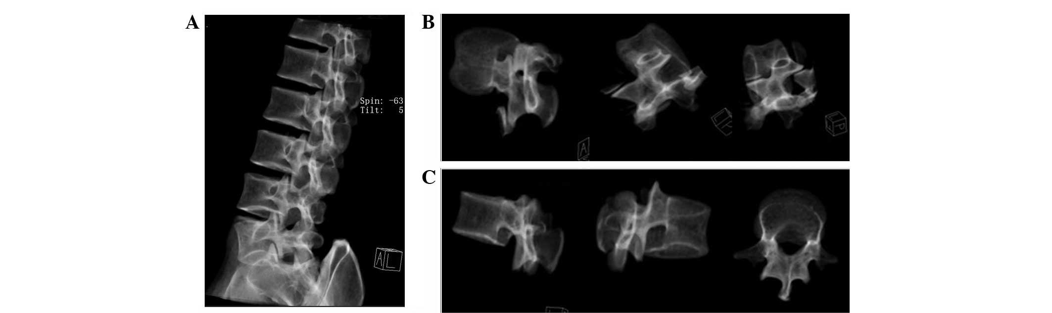
Innovative 3D modeling method processed
using Siemens syngo 3D software
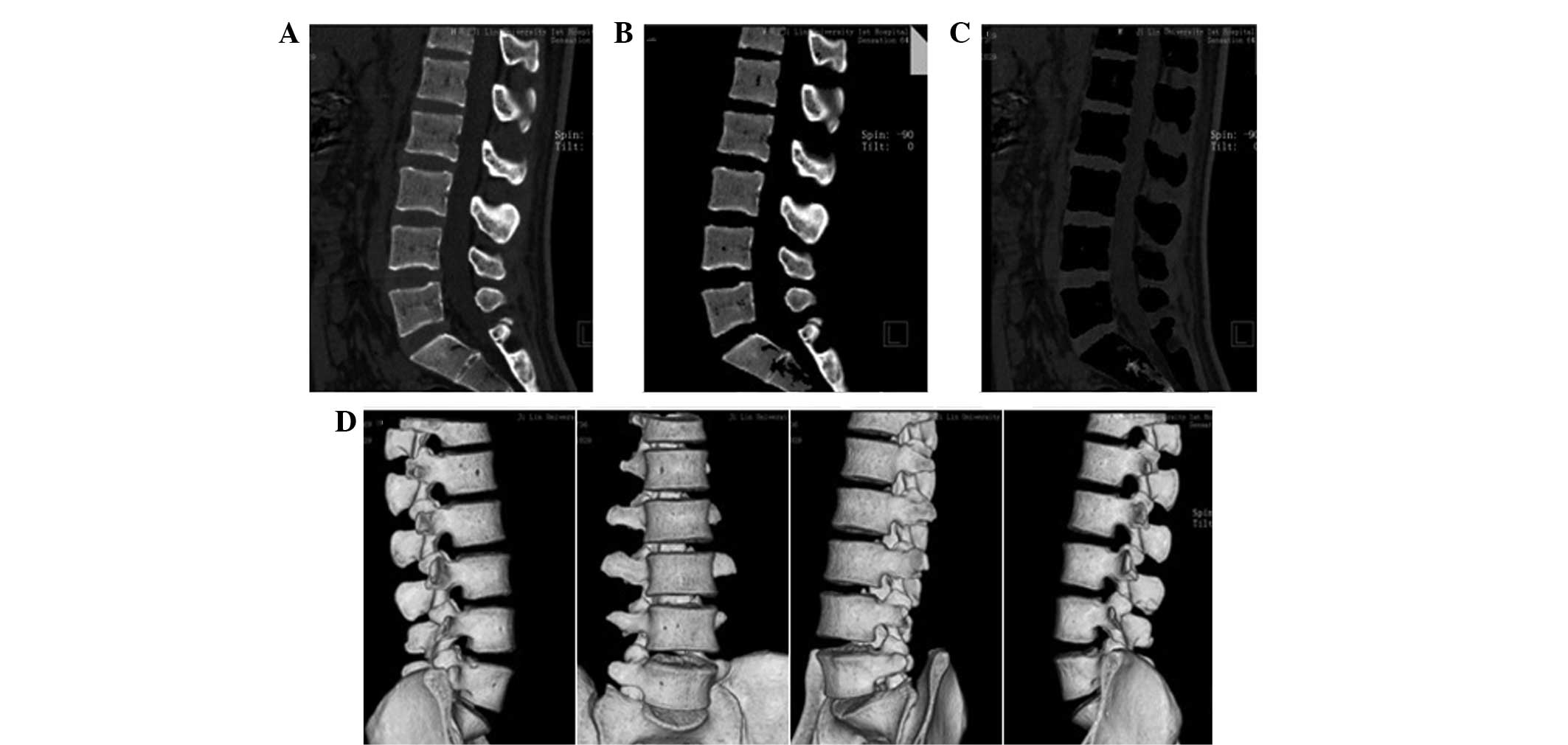
Fig. 1 shows all
the tissue markings with Fig. 1A
showing the sagittal frame of the lumbar spine prior to tissue
marking, Fig. 1B showing the
sagittal frame following bone marking and Fig. 1C showing the soft tissue marking.
Fig. 1D shows the 3D image of the
lumbar spine following tissue marking.
3D incision
Fig. 2A
demonstrates that the transparency of the bone structure
significantly facilitated the 3D incision of the lumbar spine. The
lumbar vertebra was then rotated 360° in a transparent mode to
facilitate 3D incision (Fig. 2B)
and the construction of L1 (Fig.
2C).
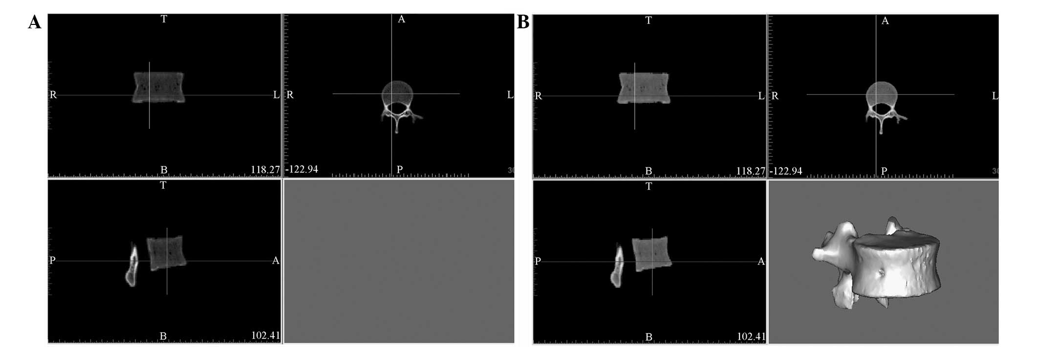
Further processing with Mimics
software
DICOM data of a single vertebra were transferred
into Mimics following processing by Siemens syngo 3D software
(Fig. 3A). The vertebra model was
constructed by further processing in Mimics (Fig. 3B). Following the removal of the
surrounding soft tissue, all bone tissue information of the
selected vertebra was obtained by adjusting the threshold of the
gray value to the minimum. As a result, the information of the
vertebral body bone tissue was completely preserved without extra
information or background (Fig.
3B).
Final model after polishing and
remeshing
Fig. 4 shows the
meshed, smoothed and remeshed model using the Magics software
included in Mimics. Fig. 4A shows
the raw model prior to polishing, Fig.
4B shows the smoothed model following polishing and Fig. 4C shows the remeshed model.
Congruence comparison between the models
constructed by traditional and innovative 3D modeling methods
Models constructed by the traditional and innovative
methods from the same raw DICOM data of a single vertebra are shown
in Figs. 5A and 5B, respectively.
The merged image of the two models (Fig. 5C) shows striking consistencies,
which indicates the accuracy and reliability of the innovative
method.
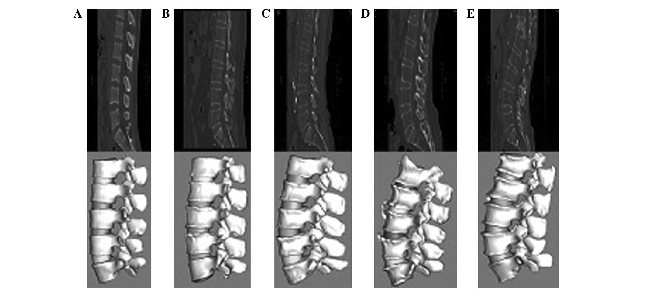
Comparison of time consumption between
traditional and innovative 3D modeling methods
Fig. 6 shows the
lumbar spine models constructed for five age groups by the
innovative method. A significant difference was observed in time
consumption of the two model construction methods. Table I shows that the time spent to
produce a contour image of five age groups using the new 3D
modeling method was generally shorter compared with that using the
traditional method. Time consumption was longer for the elderly age
groups than for younger groups, particularly when using the
traditional method. Therefore, the results indicate that the
difficulty of model construction increases with increasing age, and
time saved by the innovative method increases as the age group
increases. Constructing the model of a lumbar spine for five
consecutive vertebrae (L1–5) of an elderly osteoporotic patient
took ~24 h to complete using the traditional manual method, whereas
~2 h was spent to finish the same work with the new 3D modeling
method. Therefore, the processing time of the innovative method was
~10-times shorter than that of the traditional method. The
innovative approach markedly simplified the manual margin
discrimination and slice-by-slice incision between the vertebral
body and surrounding soft tissues. The new method also saved much
time and greatly improved the efficiency of the analysis.
 | Table IComparision of time consumption
between traditional and new methods of model construction. |
Table I
Comparision of time consumption
between traditional and new methods of model construction.
| Group | Traditional method,
h | SD traditional | New method, h | SD new | P-value |
|---|
| 20–40 years | 4.4 | 0.65 | 1.00 | 0.14 | <0.001 |
| 41–50 years | 13.0 | 1.58 | 1.58 | 0.13 | <0.001 |
| 51–60 years | 15.0 | 0.71 | 2.02 | 0.15 | <0.001 |
| 61–70 years | 20.4 | 1.14 | 2.12 | 0.08 | <0.001 |
| >70 years | 24.2 | 1.48 | 2.50 | 0.35 | <0.001 |
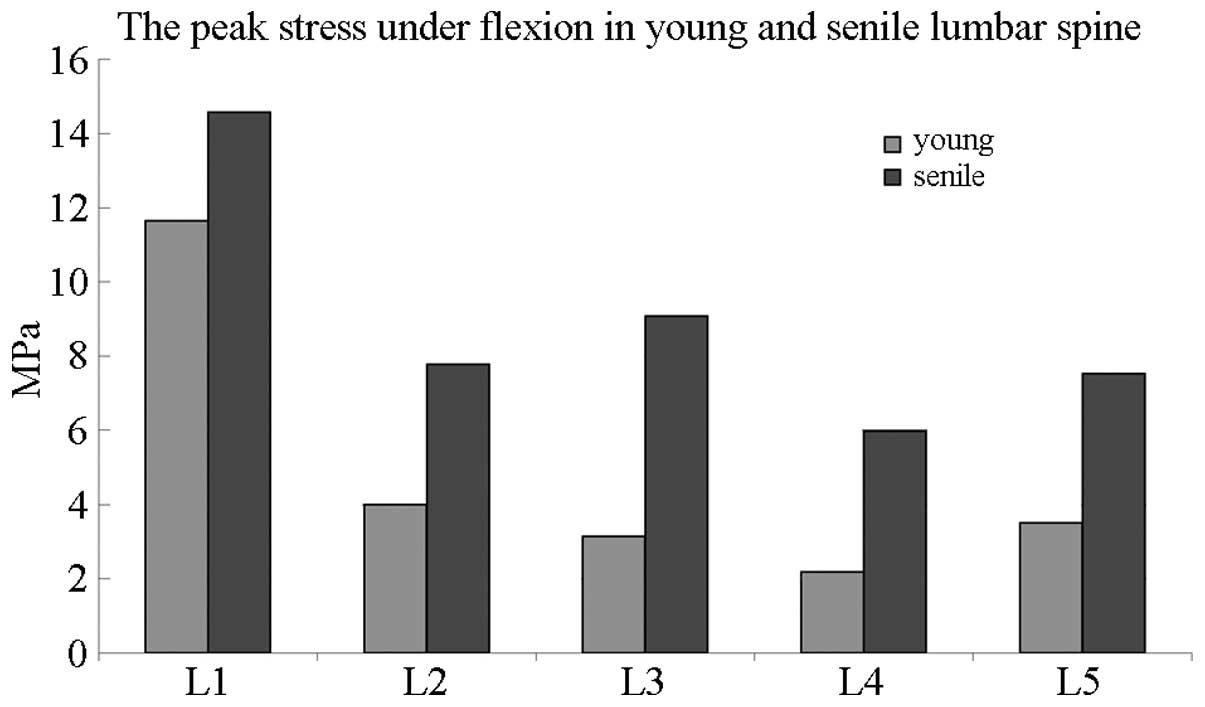
Peak stress in the lumbar spine of young
and elderly patients
Fig. 7 compares the
peak stress between elderly and young individuals in the lumbar
spine under flexion elevation. The most evident variations between
the age groups were observed from L2 to L5, with the peak stress of
elderly patients being twice as high as that of young
individuals.
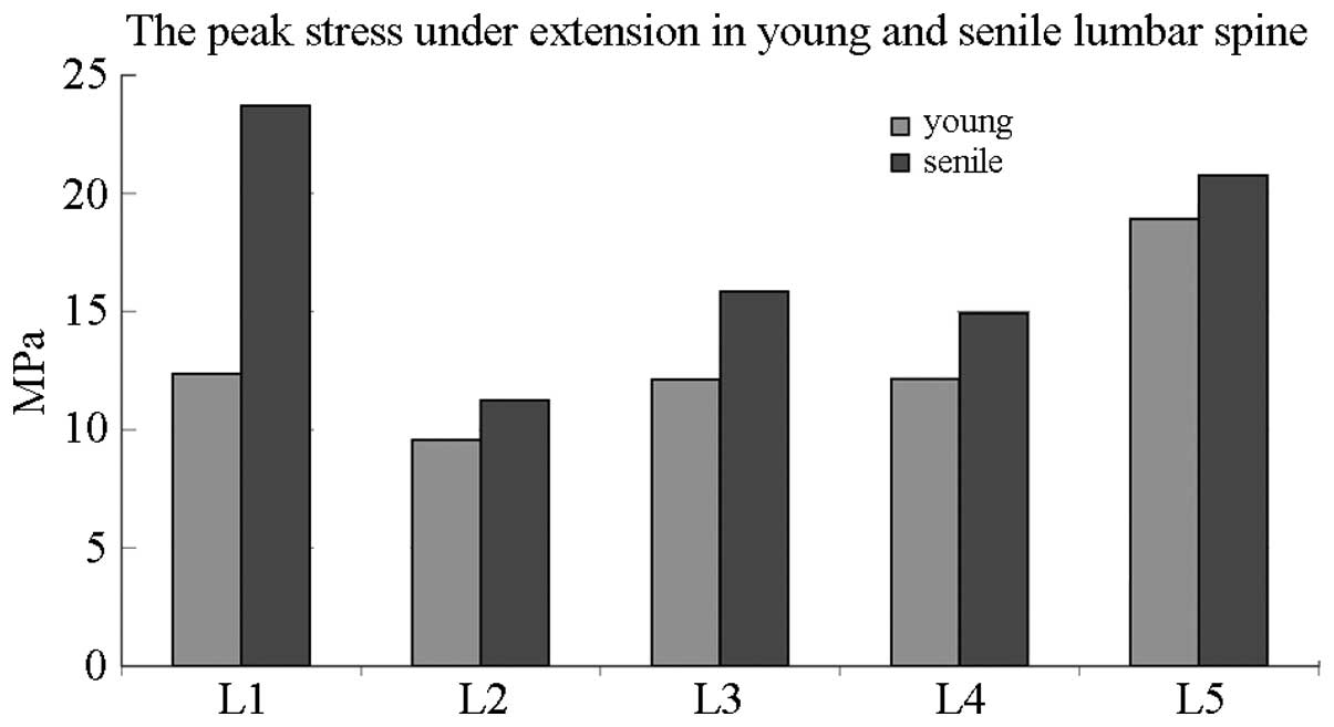
Fig. 8 compares the
peak stress between elderly and young individuals in the lumbar
spine under extension elevation. The most evident variation was
observed in the L1 of elderly patients, which showed a peak stress
twice as high as that of young patients.
Therefore, peak stress was elevated in each lumbar
vertebra under flexion and extension in elderly people.
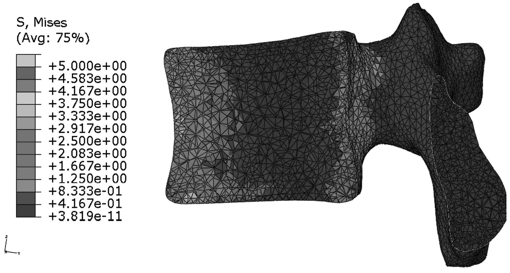
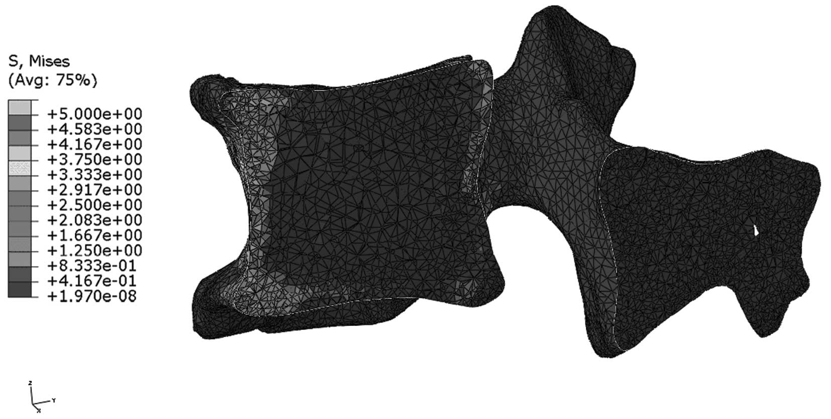
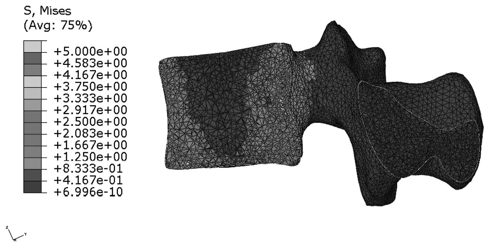
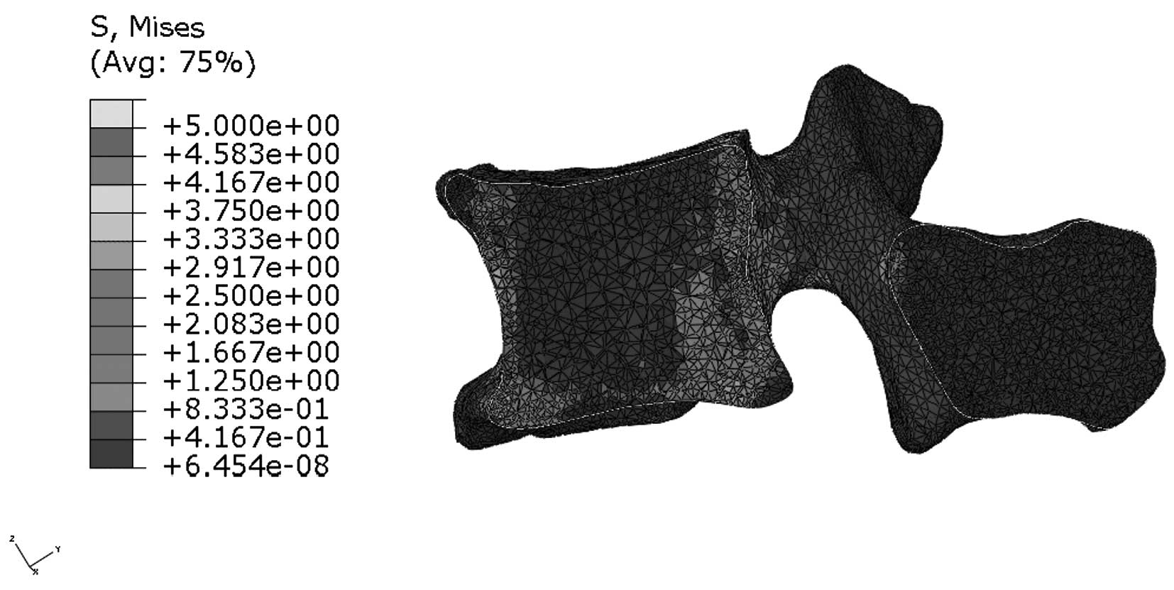
Stress distribution in the median
sagittal plane of L1
Figs. 9 and
10 indicate that stress is evenly
distributed in the entire L1 of young individuals, without stress
concentration under flexion. By contrast, the stress redistribution
in the L1 of older patients indicates stress-concentration in the
anterior cortex under flexion. Similarly, Figs. 11 and 12 show the stress redistribution in the
L1 under extension in young and elderly patients, respectively.
Stress redistribution in older patients resembles stress
concentration in the anterior cortex, whereas that of young
individuals resembles evenly distributed stress.
Discussion
In the last decade, significant development of
biomechanics has occurred. Joint application and finite element
techniques have greatly contributed to the improved understanding
of biomechanical behavior in the human body, particularly the
musculoskeletal system (16–18).
However, the modeling process remains complex. The
current method used for constructing models from a CT scan dataset
for FEA study is time-consuming and the number of samples that may
be analyzed is limited (19). The
traditional model construction method for processing a CT image
using Mimics is meticulous and tedious work since it requires the
extraction of tissues by manually drafting the contour of the
vertebrae slice-by-slice (20,21).
In addition, the application of FEA in objects with pathological
changes has resulted in difficulties with tissue-margin
discrimination for irregular pathological structures, thereby
affecting the accuracy and efficiency of the traditional method.
Manual discrimination of the contour of delicate osteoporotic
structures and irregular osteophytes in elderly patients with
typical pathological changes is ambiguous and time-consuming
(22). Subsequently, miscutting of
vertebral bone tissues often occurs (23). Stress distribution is greatly
affected by subtle alterations in anatomical structures in
pathological conditions (24).
Accordingly, bias in the stage of model construction often results
in unexpected deviations of the stress distribution in FEA, as the
final stage of biomechanical study.
Furthermore, studies have attempted to explain
stress redistribution with models based on normal anatomical
configurations in pathological conditions in the early stage of FEA
(3,6,7).
However, these studies have failed to determine the true stress
distribution in pathological conditions, particularly in cases such
as osteoporosis and irregular osteophytes, which often cause more
systemic errors. Moreover, margin-determination using a
conventional manual model construction method is extremely
time-consuming (~20 h).
In summary, the results obtained using the
traditional biomechanical FEA model construction method under
pathological conditions and the challenging manual determination of
the contours of typical pathological changes in morphology make the
traditional method tedious and prone to errors. The establishment
of an accurate and efficient method of model construction has
become an critical requirement for further FEA study under
pathological conditions. A new 3D modeling method, that pertinently
utilizes excellent multiple image post-processing with 3D
processing functions of the Siemens syngo software, was developed
to perform automatic tissue margin selection with high efficiency
and accuracy. With the post-processing of syngo software before
model construction, the soft tissue could be eliminated and the
bone tissue could be extracted both accurately and effectively.
This method also reduces the major limitations encountered when
using the traditional construction method in creating models from
pathological cases, including those encountered with elderly
patients. Following multiple image post-processing to automatically
select tissue margins, data are transferred from DICOM to Mimics,
in which the last step of model construction for FEA study is
performed. Using the new method eliminates the time-consuming
slice-by-slice processing step.
A lumbar vertebra is easily rotated 360° and may be
conveniently observed, incised and marked from any angle using the
‘Osseous Transparent Metal VP’ and ‘Osseous Shaded VP’ modes of the
new 3D modeling method. The previously cumbersome, challenging and
time-consuming task of model construction for elderly patients with
osteoporosis and degenerative osteophytes has been simplified. In
such cases, margin discrimination between the bone and soft tissues
was formerly equivocal and misleading to the naked eye due to
similarities in CT and gray values, as well as the irregular margin
of the osteophytes. However, discrimination is simple when using
the Siemens syngo 3D software, which removes the surrounding soft
tissues to show the vertebral body alone and facilitates the final
model construction in Mimics.
Comparative FEA study of the lumbar spines between
young and elderly patients, on the basis of the models constructed
by the new bionic modeling method, shows peak stress elevation in
each lumbar vertebra of the elderly. Stress was evenly distributed
throughout the vertebrae in young people, whereas stress
redistribution in the vertebrae of elderly patients was
concentrated in the anterior cortex, which explains the high
fracture risk in the elderly. The FEA results were consistent with
clinical observations, which indicated that the most common site of
lumbar vertebral fracture was generally located in the anterior
cortex of L1.
A fast and efficient method of CT image-based
modeling of the lumbar spine for FEA is described in the present
study. The model provides a 10-fold reduction in the average
processing time and utilizes automatic tissue margin discrimination
with Siemens syngo software in a 3D mode, instead of manual
discrimination with the naked eye. In addition, 3D cutting is used
instead of slice-by-slice cutting. The low speed and equivocal
margin discrimination of the traditional model construction method
does not allow the pathological analysis of a large number of
specimens. By contrast, the new 3D modeling method achieves high
efficiency and accuracy, allowing for large sample sizes and
multivertebrae analysis, thereby enabling the application of
significant statistical power in all future biomechanical studies.
The new 3D modeling method was used to simulate the genuine
mechanical situation of the lumbar spine in elderly patients, thus
explaining the high fracture risk and common fracture site
mechanism in this age group. Application of this method in FEA is
likely to greatly contribute towards the accurate establishment of
the typical characteristics of stress redistribution in any
pathological condition, thereby allowing for faster and improved
data accumulation for further fracture risk studies.
Acknowledgements
The study was supported by grants from the Leading
Multi-Disciplinary Innovation Project Basic Science Foundation of
Jilin University (nos., 450060445234 and 3R210H143428).
References
|
1
|
Turner MJ, Clough RW, Martin HC and Topp
LJ: Stiffness and deflection analysis of complex structures. J Aero
Sci. 23:805–823. 1956. View
Article : Google Scholar
|
|
2
|
Belytschko TB, Andriacchi TP, Schultz AB
and Galante JO: Analog studies of forces in the human spine:
computational techniques. J Biomech. 6:361–371. 1973. View Article : Google Scholar : PubMed/NCBI
|
|
3
|
Wang JL, Parnianpour M, Shirazi-Adl A and
Engin AE: Rate effect on sharing of passive lumbar motion segment
under load-controlled sagittal flexion: viscoelastic finite element
analysis. Theor Appl Fract Mec. 32:119–128. 1999. View Article : Google Scholar
|
|
4
|
El-Rich M, Arnoux PJ, Wagnac E, Brunet C
and Aubin CE: Finite element investigation of the loading rate
effect on the spinal load-sharing changes under impact conditions.
J Biomech. 42:1252–1262. 2009. View Article : Google Scholar : PubMed/NCBI
|
|
5
|
Hakim NS and King AI: A three dimensional
finite element dynamic response analysis of a vertebra with
experimental verification. J Biomech. 12:277–285. 1979. View Article : Google Scholar : PubMed/NCBI
|
|
6
|
Schmidt H, Heuer F, Simon U, et al:
Application of a new calibration method for a three-dimensional
finite element model of a human lumbar annulus fibrosus. Clin
Biomech (Bristol, Avon). 21:337–344. 2006. View Article : Google Scholar : PubMed/NCBI
|
|
7
|
Renner SM, Natarajan RN, Patwardhan AG, et
al: Novel model to analyze the effect of a large compressive
follower pre-load on range of motions in a lumbar spine. J Biomech.
40:1326–1332. 2007. View Article : Google Scholar : PubMed/NCBI
|
|
8
|
Rohlmann A, Bauer L, Zander T, Bergmann G
and Wilke HJ: Determination of trunk muscle forces for flexion and
extension by using a validated finite element model of the lumbar
spine and measured in vivo data. J Biomech. 39:981–989. 2006.
View Article : Google Scholar : PubMed/NCBI
|
|
9
|
Zander T, Rohlmann A, Burra NK and
Bergmann G: Effect of a posterior dynamic implant adjacent to a
rigid spinal fixator. Clin Biomech (Bristol, Avon). 21:767–774.
2006. View Article : Google Scholar : PubMed/NCBI
|
|
10
|
Zeng XL, Peng L and Bai J:
Three-dimensional finite element modeling and analysis of human
L3–L4 lumbar segment based on CT data. Beijing Biomed Eng.
26:266–269. 2007.(In Chinese).
|
|
11
|
Jiang HB: Static and dynamic mechanics
analysis on artificial hip joints with different interface designs
by the finite element method. J Bionic Eng. 4:123–131. 2007.
View Article : Google Scholar
|
|
12
|
Chevalier Y, Charlebois M, Pahra D, et al:
A patient-specific finite element methodology to predict damage
accumulation in vertebral bodies under axial compression, sagittal
flexion and combined loads. Comput Methods Biomech Biomed Engin.
11:477–487. 2008. View Article : Google Scholar
|
|
13
|
Kim TY, Kang KT, Yoon do H, et al: Effects
of lumbar arthrodesis on adjacent segments: differences between
surgical techniques. Spine (Phila Pa 1976). 37:1456–1462. 2012.
View Article : Google Scholar : PubMed/NCBI
|
|
14
|
Gong H, Wu W, Fang J, Dong X, Zhao M and
Guo T: Effects of materials of cementless femoral stem on the
functional adaptation of bone. J Bionic Eng. 9:66–74. 2012.
View Article : Google Scholar
|
|
15
|
Gu WY, Mao XG, Foster RJ, Weidenbaum M,
Mow VC and Rawlins BA: The anisotropic hydraulic permeability of
human lumbar anulus fibrosus. Influence of age, degeneration,
direction, and water content. Spine (Phila Pa 1976). 24:2449–2455.
1999. View Article : Google Scholar : PubMed/NCBI
|
|
16
|
Nadzadi ME, Pedersen DR, Callaghan JJ and
Brown TD: Effects of acetabular component orientation on
dislocation propensity for small-head-size total hip arthroplasty.
Clin Biomech (Bristol, Avon). 17:32–40. 2002. View Article : Google Scholar : PubMed/NCBI
|
|
17
|
Lu S, Xu YQ, Zhang YZ, et al: A novel
computer-assisted drill guide template for lumbar pedicle screw
placement: a cadaveric and clinical study. Int J Med Robot.
5:184–191. 2009. View
Article : Google Scholar : PubMed/NCBI
|
|
18
|
Xiao Z, Wang L, Gong H, et al:
Establishment and verification of a non-linear finite element model
for human L4–L5 lumbar segment. Biomedical Engineering and
Informatics (BMEI), 2010 3rd International Conference on IEEE.
3:1171–1175. 2010.
|
|
19
|
Francis A, Nareliya R and Kumar V:
Three-dimensional finite element analysis of human femur: A
comparative study, proceedings of all India seminar on biomedical
engineering 2012 (AISOBE 2012). Springer India. 37–48. 2013.
|
|
20
|
Sun W, Starly B, Darling A and Gomez C:
Computer-aided tissue engineering: application to biomimetic
modelling and design of tissue scaffolds. Biotechnol Appl Biochem.
39(Pt 1): 49–58. 2004. View Article : Google Scholar : PubMed/NCBI
|
|
21
|
Kuo CS, Hu HT, Lin RM, et al:
Biomechanical analysis of the lumbar spine on facet joint force and
intradiscal pressure-a finite element study. BMC Musculoskelet
Disord. 11:1512010. View Article : Google Scholar : PubMed/NCBI
|
|
22
|
Xiao Z, Wang L, Gong H and Zhu D:
Biomechanical evaluation of three surgical scenarios of posterior
lumbar interbody fusion by finite element analysis. Biomed Eng
Online. 11:312012. View Article : Google Scholar : PubMed/NCBI
|
|
23
|
Harrysson OL, Hosni YA and Nayfeh JF:
Custom-designed orthopedic implants evaluated using finite element
analysis of patient-specific computed tomography data:
femoral-component case study. BMC Musculoskelet Disord. 8:912007.
View Article : Google Scholar
|
|
24
|
Niemeyer F, Wilke HJ and Schmidt H:
Geometry strongly influences the response of numerical models of
the lumbar spine - a probabilistic finite element analysis. J
Biomech. 45:1414–1423. 2012. View Article : Google Scholar : PubMed/NCBI
|