Introduction
Severe titanium mesh cage (TMC) subsidence (>3
mm) is the most common postoperative complication in anterior
cervical corpectomy and fusion (ACCF) (1-7),
which occurs in up to 30.8% of patients. Major loss of
intervertebral body height (IBH) notably alters cervical alignment,
increases the stress load of fixation and decreases the volume of
the spinal canal and intervertebral foramen (4,7,8). These
pathological changes can result in severe complications, such as
kyphosis, nerve recompression and internal fixation failure, which
greatly affect surgical outcomes (2-4,7).
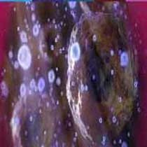
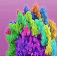
The sharp footprints and flat end of conventional
TMCs play important roles in subsidence (Figs. 1 and 2) (2,4,7,9).
These design defects lead to a very small contact area at the
TMC-endplate interface (TEI), which results in high stress
concentration and causes the TMC to perforate easily into the
endplate (4,7,10). To
increase the contact area and thus homogeneously distribute the
stress at the TEI (11-13),
several cages with enlarged end surfaces have been applied in ACCF
(7,14,15).
However, even if the end surface is enlarged, the rate of TMC
subsidence is frequently still high at the last follow-up (7,14,15),
primarily because the ends of these devices are still flat, and the
actual contact area at the TEI does not effectively increase
(4,10,16).
Therefore, to increase the contact area and reduce the
concentration of stress at the TEI, the geometries of the TMC ends
should be designed such that they are adaptive to the endplate.
The aim of the present study was to design an
optimal quadrate anatomically adaptive titanium mesh cage (AA-TMC)
that achieves good geometrical matching with the TEI, IBH and
intervertebral body angle (IBA) in one- and two-level ACCF. To
ensure good geometrical matching, the end shape, height and
diameter of the AA-TMC were identified based on the morphological
measurements of cervical geometries. After being constructed, the
AA-TMC was implanted into cervical cadaveric specimens and
underwent computed tomography (CT) tests to further assess its
effects on TEI matching and the maintenance of IBA and IBH.
Materials and methods
Endplate geometry measurements
The present study was approved by the Ethics
Committee of Xi'an Jiaotong University Second Affiliated Hospital
(Xi'an, China). The cervical CT images of 71 individuals were
obtained by searching the CT database in Xi'an Jiaotong University
Second Affiliated Hospital (from April 2016 to July 2017). The
images were imported into Mimics Innovation Suite 17 (Materialise
NV) to measure the endplate geometries. Individuals with obvious
degeneration, obvious osteophytes, fracture, infection or
metastasis were excluded. Finally, a total of 54 subjects were
included for data measurement (35 males and 19 females; average
age, 56.54±11.34 years; age range, 37-81 years).
The interior endplates (IEPs) from C3 to C6 and the
superior endplates (SEPs) from C4 to C7 were included for analysis.
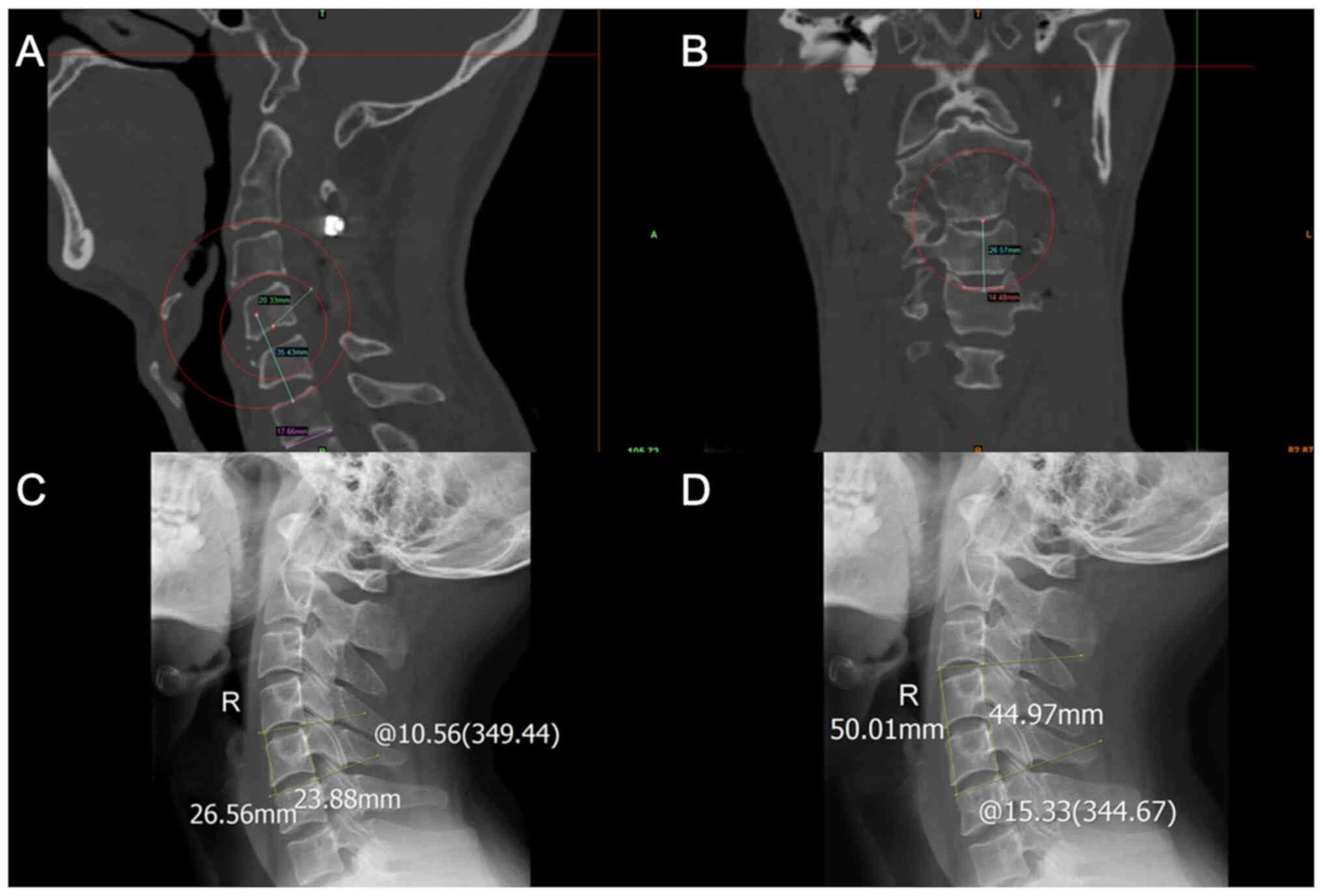
In total, five parameters were measured (Fig. 3): i) The middle sagittal
anteroposterior diameter (APD); ii) the middle coronal transverse
diameter (TD); iii) the middle sagittal radius of the endplate; iv)
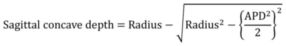
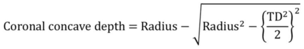
the middle coronal radius of the endplate; and v) the concave depth
of the endplate. When measuring the endplate radius, if the shape
of the endplate was not obviously arched, an arc was drawn through
the deepest point of the endplate, as well as the end points of the
APD or TD. This arc approximately and quantitatively described the
shape of the endplate, which was considered arched when the concave
depth was >1 mm. The concave depth was calculated as
follows:
IBA and IBH measurements
The cervical X-rays of 88 young individuals were
collected by searching the X-ray database in Xi'an Jiaotong
University Second Affiliated Hospital from March 2017 to July 2018,
and were used to measure the IBA and IBH of the C4, C5, C6, C4-5
and C5-6 levels. The IBA of C4 referred to the angle between the C3
inferior endplate and C5 superior endplate. The IBH of C4 referred
to the distance between the C3 inferior endplate and C5 superior
endplate. The IBA of C5 referred to the angle between C4 inferior
endplate and C6 superior endplate. The IBH of C5 indicated the
distance between the C4 inferior endplate and C6 superior endplate.
The IBA of C6 referred to the angle between the C5 inferior
endplate and C7 superior endplate. The IBH of C6 referred to the
distance between the C5 inferior endplate and C7 superior endplate.
The IBA of C4-5 referred to the angle between the C3 inferior
endplate and C6 superior endplate. The IBH of C4-5 referred to the
distance between the C3 inferior endplate and C6 superior endplate.
The IBA of C5-6 referred to the angle between the C4 inferior
endplate and C7 superior endplate. The IBH of C5-6 referred to the
distance between the C4 inferior endplate and C7 superior endplate.
The measurement methods are presented in Fig. 3. Patients with cervical
straightening, kyphosis, fracture, intervertebral space narrowing,
obvious osteophytes, infection or metastasis were excluded.
Finally, a total of 74 subjects were included for IBA and IBH
measurements (44 males and 30 females; average age, 33.88±7.6
years; age range, 27-77 years).
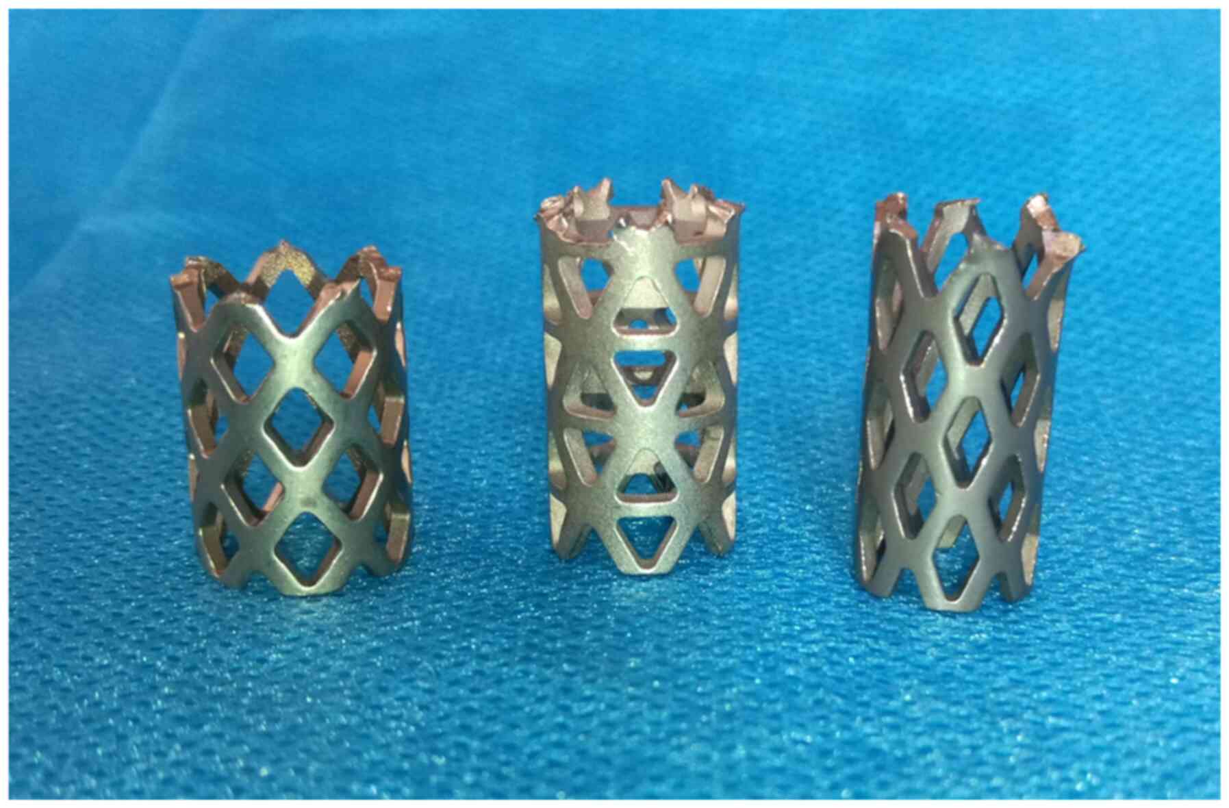
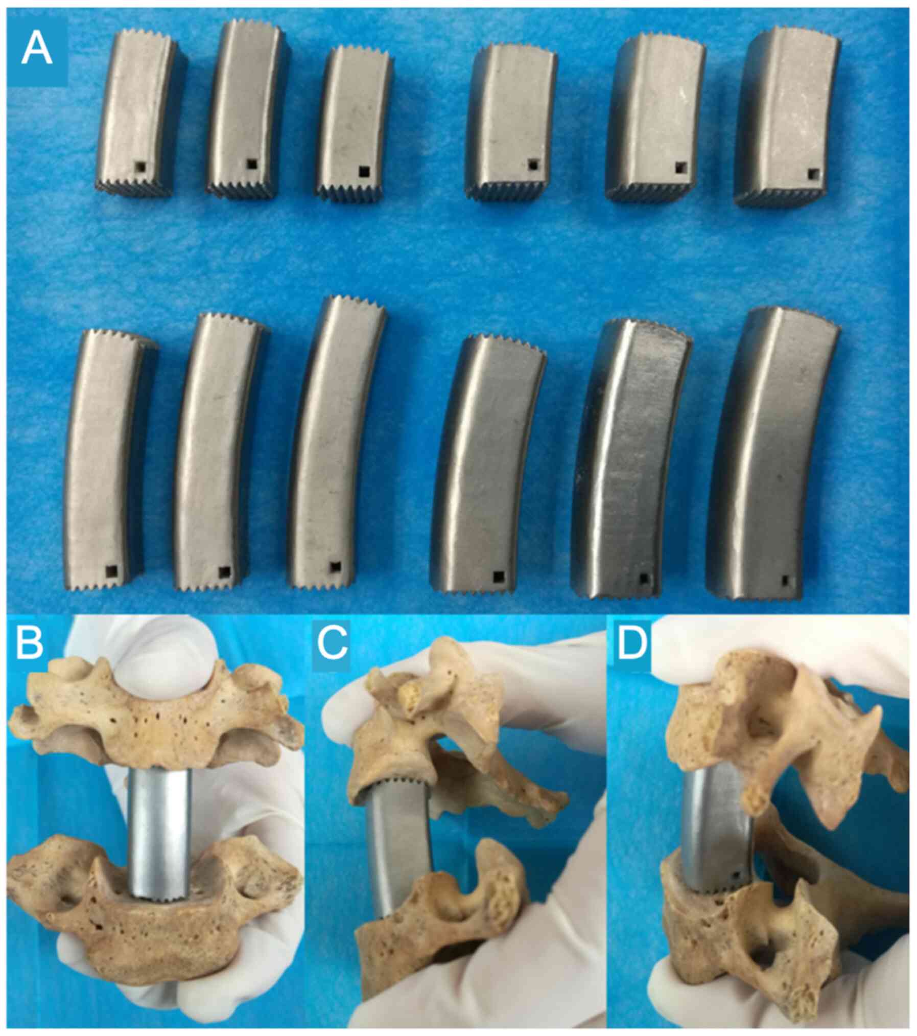
Description of AA-TMC
The shape of the AA-TMC was designed based on the
average values of the measured parameters (APD, TD, sagittal
radius, coronal radius, IBA and IBH). Both ends of the AA-TMC were
domed. In the side view, the TMC was designed to be curved, and the
curve of the cage was determined by IBA and IBH. In the axial view,
the AA-TMC was quadrate. A total of 12 AA-TMCs with different sizes
were designed with the following dimensions (parameters, height x
anteroposterior diameter x transversal diameter; Fig. 4): 23x12x12, 25x12x12, 27x12x12,
23x14x14, 25x14x14, 27x14x14, 40x12x12, 43x12x12, 46x12x12,
40x14x14, 43x14x14 and 46x14x14 mm. The surface aeras of the
inferior and superior TMC ends were the 0.84 cm2 and
0.91 cm2, respectively. All AA-TMCs were constructed
using a selective laser melting 3D-printing machine (BLT-S300;
Xi'an Bright Additive Technologies Co., Ltd.).
Measurements of TEI matching degree,
postoperative IBA and IBH
A total of 18 formalin-fixed cervical cadaveric
specimens were obtained from the Department of Human Anatomy and
Tissue Embryology of Xi'an Jiaotong University (11 males and 7
females; average age, 67.83±13.37 years; age range, 42-85 years).
All of the specimens were examined by X-ray to exclude evident
osteophytes, fracture, infection and metastasis. Written informed
consent for the use of these tissues was obtained from relatives
prior to sample collection. These specimens were randomly assigned
to 3 groups (n=6/group): C4 corpectomy, C5 corpectomy and C6
corpectomy. After one-level corpectomy, the surgeon chose a
suitably sized AA-TMC and inserted it into the intervertebral body
space. The specimen then underwent CT scanning (120 kV; 200 mA;
slice thickness, 1.25 mm). The images were imported into Mimics 17
to assess IBA, IBH and TEI matching. Subsequently, the six
specimens in the C5 corpectomy group were randomly reassigned into
the C4-5 corpectomy and the C5-6 corpectomy groups. The six
specimens in the C4 corpectomy group were reassigned into the C4-5
corpectomy group and the six specimens in the C6 corpectomy group
were reassigned into the C5-6 corpectomy group. The two-level ACCF
surgical procedure and the same CT evaluations were then performed
in each group. The evaluation of IBA, IBH and TEI matching was
similar to that for one-level corpectomy.
TEI matching evaluation was performed in the middle
sagittal and coronal planes of the endplate. The matching outcomes
were classified into 3 grades: Grade I, maximum interval between
the TMC and endplate <0.5 mm; grade II, maximum interval between
0.5-1 mm; and grade III, maximum interval >1 mm.
Statistical analysis
All measurement data are presented as the mean ± SD.
SPSS 18.0 was used for statistical analysis. One-way analysis of
variance was applied to compare the APD, TD, IBA, IBH, sagittal and
coronal radii, and the sagittal and coronal concave depths among
groups, with Bonferroni post hoc test subsequently used. Fisher's
exact test was used to compare the arched rates among groups, with
Bonferroni's correction applied when using multiple Fisher's exact
tests for multiple comparisons. P<0.05 was considered to
indicate a statistically significant difference.
Results
Endplate geometries
The outcomes of the endplate geometries obtained
from the patients' CT images are presented in Tables I and II. In general, the APDs and TDs of the
IEP progressively increased from C3 IEP (16.20±1.81 and 15.89±1.69
mm, respectively) to C6 IEP (17.23±1.74 and 21.46±2.29 mm,
respectively). The APDs and TDs of the SEP progressively increased
from C4 SEP (15.31±1.92l and 14.30±1.55 mm, respectively) to C7 SEP
(16.42±1.78 and 18.54±2.04 mm, respectively). The mean surface
areas of the SEP and IEP were 2.56 and 3.04 cm2,
respectively (mean ATP multiplied by mean TD). Regarding the
sagittal radii of the endplate, the IEP increased from C3 IEP
(19.51±6.59 mm) to C6 IEP (24.21±9.33 mm), and the SEP reduced from
C4 SEP (135.78±58.91 mm) to C7 SEP (90.00±57.29 mm). The coronal
radii of the C3 and C4 IEPs were 113.6±57.09 and 126.70±57.23 mm,
respectively, which were significantly higher than those of C5 and
C6 (79.98±37.90 and 68.48±25.86 mm, respectively). The coronal
radius of C7 SEP was 101.33 mm, which was significantly higher than
those of the SEPs of C4, C5, and C6 (87.18±66.34, 73.56±41.25, and
94.97±60.23 mm, respectively). In addition, the mean depths of the
IEPs in the sagittal and coronal planes were 1.80±0.61 and
0.59±0.40 mm, respectively. The mean depths of the SEPs in the
sagittal and coronal planes were 0.39±0.29 and 0.51±0.34 mm,
respectively. Most of the IEPs in the sagittal plane were arched
(93.8%), whereas the majority of the IEPs in the coronal plane, and
the majority of the SEPs in the sagittal and coronal planes were
flat (82.9, 94.8 and 93.8%, respectively).
 | Table IMiddle sagittal plane endplate shape
parameters. |
Table I
Middle sagittal plane endplate shape
parameters.
| A, IEP |
|---|
| Level | APD, mm | Radius, mm | Depth, mm | Arched/Total (%) |
|---|
| C3 (n=44) |
16.20±1.81a,b |
19.51±6.59c,d | 1.91±0.51 |
44/44(100)i,j |
| C4 (n=53) | 16.65±2.18 |
21.06±7.97e | 1.88±0.54 | 52/53
(98.1)k |
| C5 (n=48) | 17.10±2.19 | 27.40±11.04 |
1.58±0.66f,g,h | 40/48(80) |
| C6 (n=48) | 17.23±1.74 | 24.21±9.33 | 1.82±0.67 | 43/48 (89.6) |
| Total (n=193) | 16.8±2.02 | 23.07±9.34 | 1.80±0.61 | 181/193 (93.8) |
| B, SEP |
| Level | APD, mm | Radius, mm | Depth, mm | Arched/Total
(%) |
| C4 (n=51) |
15.31±1.92l,m,n | 135.78±58.91 |
0.27±0.14r,s | 0/51 (0) |
| C5 (n=54) | 16.14±2.26 | 133.11±74.83 |
0.35±0.3t | 2/54 (3.6) |
| C6 (n=48) | 16.49±2.22 | 115.63±70.71 | 0.45±0.35 | 1/48 (2.1) |
| C7 (n=40) | 16.42±1.78 |
90.00±57.29o,p,q | 0.51±0.30 | 4/40(10) |
| Total (n=193) | 16.06±2.11 | 120.53±68.17 | 0.39±0.29 | 10/193 (5.2) |
| Table IIMiddle coronal plane endplate shape
parameters. |
Table II
Middle coronal plane endplate shape
parameters.
| A, IEP |
|---|
| Level | TD, mm | Radius, mm | Depth, mm | Arched/Total
(%) |
|---|
| C3 (n=44) |
15.89±1.69a |
113.6±57.09b,c |
0.37±0.23d | 2/44 (4.5) |
| C4 (n=53) |
17.00±1.86a |
126.70±57.23b,c |
0.39±0.33e | 4/53 (7.5) |
| C5 (n=48) |
17.94±2.22a | 79.98±37.90 |
0.64±0.37f-h | 6/48 (12.5) |
| C6 (n=48) |
21.46±2.29a | 68.48±25.86 | 0.95±0.33 | 21/48
(43.75)i-k |
| Total (n=193) | 18.09±2.89 | 97.61±52.1 | 0.59±0.40 | 33/193 (17.1) |
| B, SEP |
| Level | TD, mm | Radius, mm | Depth, mm | Arched/Total
(%) |
| C4 (n=51) |
14.30±1.55l | 87.18±66.34 | 0.48±0.33 | 4/51 (7.8) |
| C5 (n=54) |
14.81±1.70m |
73.56±41.25q,r | 0.48±0.30 | 1/54
(1.8)s |
| C6 (n=48) | 16.82±2.50 | 94.97±60.23 | 0.51±0.28 | 3/48 (6.3) |
| C7 (n=40) |
18.54±2.04n-p | 101.33±51.70 | 0.59±0.44 | 6/40(15) |
| Total | 15.94±2.55 | 88.22±56.17 | 0.51±0.34 | 12/193 (6.2) |
IBA and IBH of young individuals
The mean IBH and IBA values after one-level ACCF
were 23.90±2.18 mm and 11.62±2.67˚, respectively. In addition, the
mean IBH and IBA values after two-level ACCF were 42.93±3.51 mm and
15.63±5.06˚, respectively. No statistically significant differences
were observed between the included levels (Table III).
| Table IIIMiddle coronal plane IBH and IBA. |
Table III
Middle coronal plane IBH and IBA.
| A, One level |
|---|
| Level | IBH, mm | IBA, ˚ |
|---|
| C4 (n=74) | 24.15±2.32 | 11.67±2.67 |
| C5 (n=74) | 23.72±2.11 | 11.40±2.82 |
| C6 (n=72) | 23.83±2.12 | 11.78±2.54 |
| Total | 23.90±2.18 | 11.62±2.67 |
| B, Two level |
| Level | IBH, mm | IBA, ˚ |
| C4-5 (n=74) | 42.85±3.86 | 15.80±5.05 |
| C5-6 (n=72) | 43.01±3.14 | 15.42±5.09 |
| Total | 42.93±3.51 | 15.63±5.06 |
TEI matching degrees and postoperative
IBA and IBH
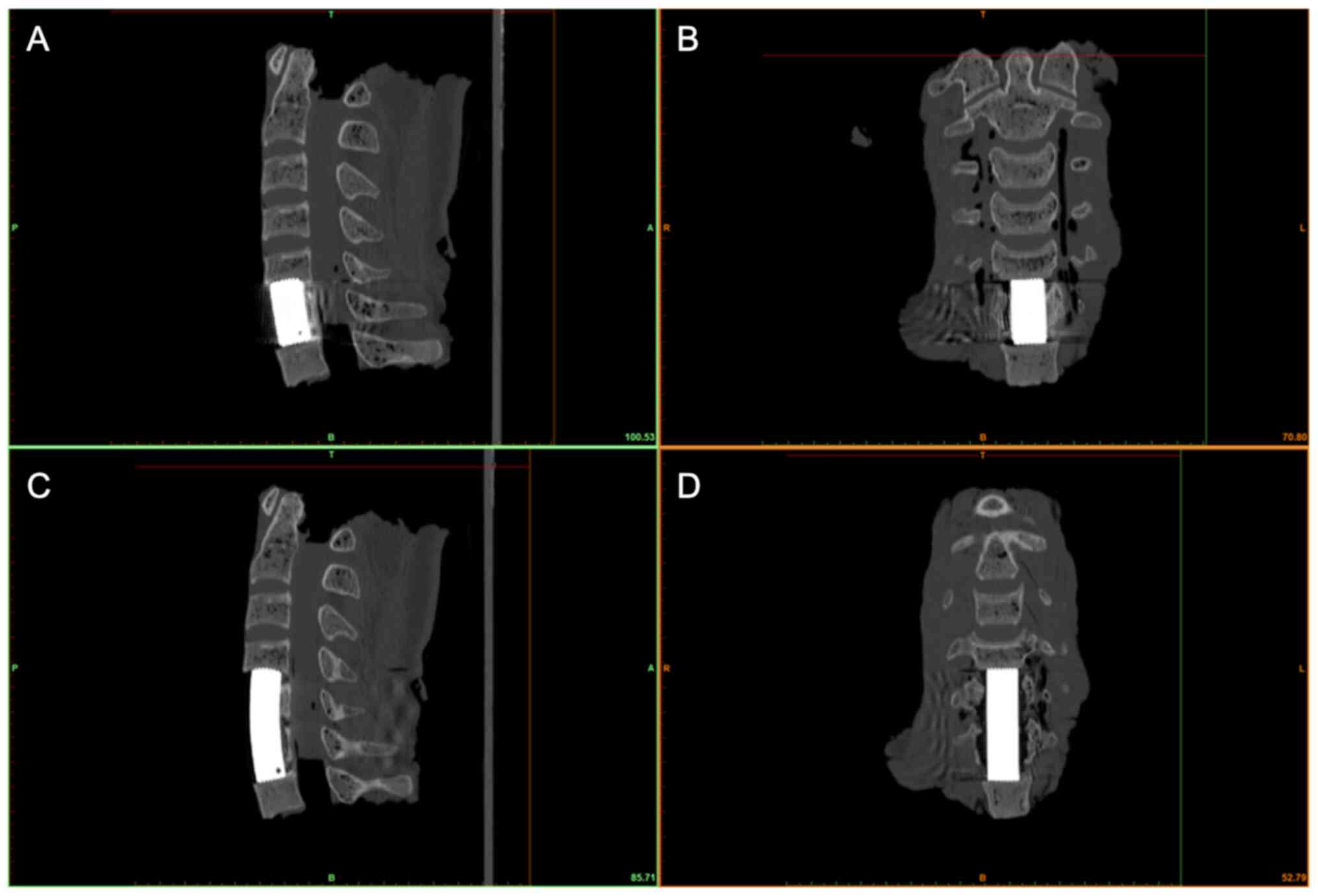
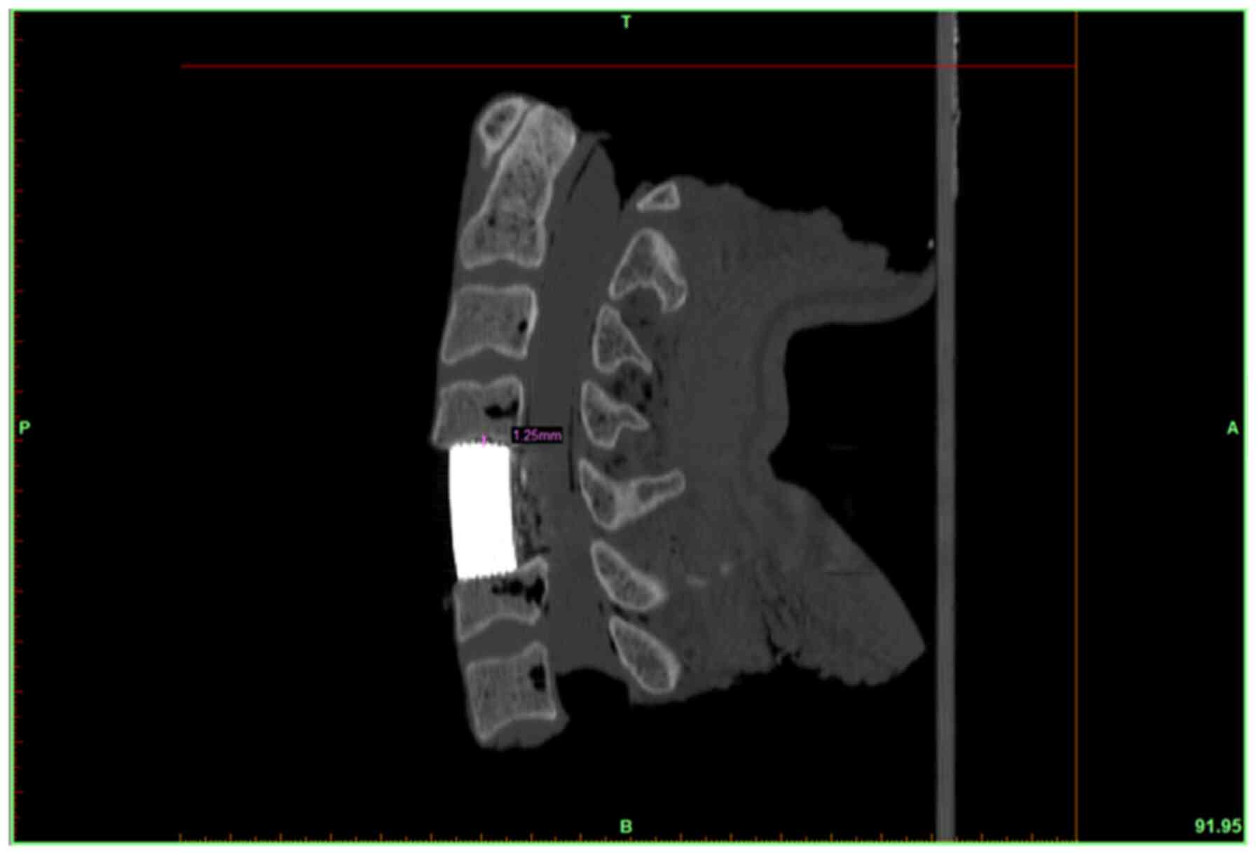
The outcomes of the TEI matching classification are
shown in Tables IV and V. For one-level ACCF, 91.7% of the TEIs
were classified as grade I, and 3.8% of the TEIs were classified as
grade II (Figs. 5A and B, and 6).
In two-level ACCF, 94.4% of the TEIs were classified as grade I
(Fig. 5C and D), and 1.4% of the TEIs were classified as
grade II. For both one- and two-level ACCF, 93.1% of the TEIs were
classified as grade I. A total of 2.7 and 4.2% of the TEIs were
classified as grades II and III, respectively. After one-level
ACCF, the mean IBH and IBA values were 24.24±1.15 mm and
12.24±0.65˚, respectively. After two-level ACCF, the mean IBH and
IBA values were 42.79±1.70 mm and 16.26±1.27˚, respectively
(Table VI). No statistically
significant differences were found between the included levels for
postoperative IBA or IBH.
| Table IVTitanium mesh cage-endplate matching
classification (one-level anterior cervical corpectomy and
fusion). |
Table IV
Titanium mesh cage-endplate matching
classification (one-level anterior cervical corpectomy and
fusion).
| A, Sagittal
plane |
|---|
| Grade | IEP, n (%) | SEP, n (%) |
|---|
| I | 15 (83.3) | 17 (94.4) |
| II | 1 (5.6) | 1 (5.6) |
| III | 2 (11.1) | 0 (0) |
| B, Coronal
plane |
| Grade | IEP, n (%) | SEP, n (%) |
| I | 17 (94.4) | 17 (94.4) |
| II | 0 (0) | 1 (5.6) |
| III | 1 (5.6) | 0 (0) |
| Table VTitanium mesh cage-endplate matching
classification (two-level anterior cervical corpectomy and
fusion). |
Table V
Titanium mesh cage-endplate matching
classification (two-level anterior cervical corpectomy and
fusion).
| A, Sagittal
plane |
|---|
| Grade | IEP (%) | SEP (%) |
|---|
| I | 16 (88.9) | 18(100) |
| II | 0 (0) | 0 (0) |
| III | 2 (11.1) | 0 (0) |
| B, Coronal
plane |
| Grade | IEP (%) | SEP (%) |
| I | 17 (94.4) | 17 (94.4) |
| II | 0 (0) | 1 (5.6) |
| III | 1 (5.6) | 0 (0) |
| Table VIPostoperative middle coronal plane
IBH and IBA. |
Table VI
Postoperative middle coronal plane
IBH and IBA.
| A, One-level
ACCF |
|---|
| Level | IBH, mm | IBA, ˚ |
|---|
| C4 (n=6) | 24.36±1.30 | 12.25±0.89 |
| C5 (n=6) | 24.12±1.05 | 12.31±0.59 |
| C6 (n=6) | 24.25±1.29 | 12.17±0.52 |
| Total | 24.24±1.15 | 12.24±0.65 |
| B, Two-level
ACCF |
| Level | IBH, mm | IBA, ˚ |
| C4-5 (n=9) | 43.12±1.81 | 16.37±1.47 |
| C5-6 (n=9) | 42.46±1.63 | 16.15±1.12 |
| Total | 42.79±1.70 | 16.26±1.27 |
Discussion
The present study showed that 93.1% of the TEIs were
<0.5 mm (grade I). This proximity at the TEI ensured a maximum
increase in contact and a homogeneous stress distribution at the
TEI, which is beneficial to subsidence resistance. Additionally,
with the use of the AA-TMC, IBA and IBH were successfully
reconstructed in one- and two-level ACCF, suggesting that the
AA-TMC may help to achieve sufficient neural decompression and
lordosis at the surgical level. Furthermore, the new AA-TMC was
designed with a quadrate shape, which is considered to be
advantageous over the conventional cylindrical TMC (9,12,17,18).
First, a quadrate-shaped AA-TMC has a greater contact area with the
posterior part of the endplate, increasing the mechanical strength
at the TEI (12,17). Second, the quadrate AA-TMC has a
larger volume for bone grafting (9,18).
Last, both sides of the AA-TMC are flat, which significantly
increases the contact area with the remaining vertebral body and
facilitates bony fusion (9,18).
Various morphological studies, as well as the
present study, have revealed that the cervical endplate is not
simply flat (10,19-21);
rather, most IEPs are arched (10,21).
Although most SEPs are considered relatively flat, they still
exhibit a concave depth of 0.39-0.69 mm (19,20).
Therefore, the flat end of conventional TMCs do not match well with
the endplate, leading to a very small contact area and high stress
concentration at the TEI (4,7,10).
Therefore, the ends of the AA-TMC were designed based on the mean
values of the endplate shape parameters to optimize the contact
area at the TEI. The results showed that a good matching rate at
the TEI was successfully obtained for the AA-TMC, and 93.1% of the
new TMC made close contact with the endplate (<0.5 mm), thus
alleviating the stress concentration at the TEI and effectively
resisting subsidence. However, 4.2% of the TEIs still exhibited a
large interval (>1 mm, grade III); thus, their mechanical
strength may decrease. In some cases, mismatch is inevitable;
matching 100% of the endplates for a fixed-shape AA-TMC is
impossible due to the large variations in endplate radius, concave
depth and concave apex location among cervical endplates (10,19-21).
TEI matching is classified based on the thickness of
the endplate, which ranges from 0.65 to 1.35 mm (22,23). A
grade I TEI allows the footprints that initially contact the
endplate to subside by only 0.5 mm, which is ~50% of the endplate
thickness; as such, the integrity of the endplate is not severely
damaged (22,23). Additionally, due to slight
subsidence, the interval disappears, which results in a significant
increase in the contact area and further alleviates the stress
concentration at the interface (11-13).
However, if the interval exceeds 1 mm, the footprints that
initially contact the endplate may perforate into the cancellous
bone before the interval disappears, severely damaging the
mechanical strength of the endplate (24).
In the present study, analysis of historical CT
images was performed to measure endplate geometries, whereas X-ray
images were used to measure IBA and IBH; there were several reasons
for these decisions. First, measuring these parameters using the CT
images was more practical than using the X-ray images, particularly
for the TD. Second, a previous study indicated that the depth of
the endplate gradually increases with age (25). Endplate geometries in the elderly
may be slightly different from those in younger populations. The CT
images in the present study were obtained from elderly patients,
whereas the X-ray images were obtained from young individuals; as
ACCF is more frequently performed in the elderly (7-9),
CT images were used to measure APD and TD to fit the endplate
geometries of elderly patients. In addition, the cervical segmental
alignment in young individuals was straighter compared with that in
elderly patients. Therefore, IBA and IBH were measured in the X-ray
images of young individuals.
In addition to simulating the endplate shape,
simulating the IBA of the surgical segment in the TMC design also
determines the degree of TEI matching (2,9,18). Due
to the IBA, the SEP is in an oblique position, which causes
conventional TMCs to contact the SEP at the posterior region
(4,6,7). This
geometric mismatch produces a high stress concentration at the
posterior region and causes most of the subsidence to occur at the
posterior-inferior part of the TMC (4,6).
Therefore, the IBA must be simulated in the TMC design to ensure
good TEI matching. Our previous study reported that simulating the
IBA in the TMC can improve the maximum load of the endplate by
32.6% compared with in conventional TMCs, thus effectively
improving the subsidence resistance (18). In the present study, the AA-TMC was
designed with a curved shape to simulate the IBA of the surgical
segments and to ensure good matching at the TEI. Additionally, the
curved AA-TMC can be aligned with the cervical lordosis, ensuring
that the AA-TMC is located inside the residual vertebral body after
multilevel corpectomy.
Simulating the IBA in an AA-TMC can successfully
maintain cervical lordosis (2,9).
Although using conventional TMCs can achieve normal IBA by the
final follow-up, the IBA was significantly reduced compared with
the IBA immediately after surgery (2,6).
Restoration of a normal IBA depends on the TMC subsidence at the
posterior-inferior region (2,6). In
contrast, by using an AA-TMC, the IBA of the surgical segment can
be restored to normal immediately after surgery (2,9).
Additionally, due to the effective increase in the TEI contact
area, the IBH of the surgical segment can be well maintained in the
long term (2,9). In the present study, postoperative IBA
and IBH values using cadaveric specimens were consistent with the
values of young individuals. Thus, combined with the advantage of
subsidence resistance, the new AA-TMC reported in the present study
may ensure that the surgical segment achieves sufficient neural
decompression and maintains cervical lordosis at all times.
Increasing the end surface of the TMC is also
beneficial for preventing subsidence by helping to distribute the
stress homogeneously from the cranial region to the endplate
(11-13).
However, over-enlarging the end surface may impact the fusion rate
(26). Thus, bony fusion and
mechanical strength must be balanced to achieve optimal outcomes
for both (26). Previous
biomechanics studies revealed that when the implant end reaches 30%
of the endplate surface area, the maximum compressive load at the
interface is similar to that at an implant end with a much larger
surface area (18,26). As presented in the results, the mean
surface areas of the SEP and IEP were 2.56 and 3.04 cm2.
Correspondingly, ~0.84 and ~0.91 cm2 of the surface
areas of the inferior and superior TMC ends, respectively, could
produce a sufficient compressive load to resist subsidence and
leave sufficient space for bony fusion. In the present study, only
an outline of the TMC was designed and constructed, as the primary
aim of the study was to assess the effects of the new TMC on TEI
matching, and restoration of segmental IBA and IBH. Thus, the TMC
should be further developed to include an appropriate autograft
space for clinical use.
The present study has several limitations. First,
the sample sizes of the cadaveric specimens in each one-level
corpectomy group were small. A small sample size may result in
selection bias and affect the measurement results of the matching
degree, IBA and IBH. Second, further biomechanical studies using
the AA-TMC for vertebral body reconstruction in ACCF should be
performed to assess the stability and durability of the surgical
construct in detail.
The new quadrate AA-TMC, which was designed based on
cervical anatomical parameters, successfully matched well with the
endplate, and restored the normal IBA and IBH; thus, this new
AA-TMC may be beneficial for preventing subsidence, and maintaining
sufficient neural decompression and lordosis. Due to these
advantages, the new TMC is advocated for use in ACCF to include an
autograft space after further development.
Acknowledgements
The authors would like to thank Dr Quanxin Yang and
Dr Xiaohui Li (both Department of Radiology, Second Affiliated
Hospital of Xi'an Jiaotong University) for their help in the CT and
X-ray data search. The authors would also like to thank Dr Xiaoqian
Zhou (Department of Radiology, Second Affiliated Hospital of Xi'an
Jiaotong University) for her help with the CT scans of the
cadaveric cervical spine specimens.
Funding
Funding: This work was supported by the National Natural Science
Foundation of China (grant no. 81571209). No benefits in any form
were received from a commercial party during the course of this
work.
Availability of data and materials
All data generated or analyzed during this study are
included in this published article.
Authors' contributions
TL wrote the paper and designed the study as well as
performed the ACCF surgery and data collection. YW performed the
ACCF surgery and data collection. ZG and JL examined the CT and
X-ray images and performed the image measurements. NL and CL
performed the statistical analysis. XH designed and supervised the
study. TL, YW, ZG, JL, NL, CL and XH confirm the authenticity of
all the raw data. All authors have read and approved the final
manuscript.
Ethics approval and consent to
participate
The present study was approved by the Ethics
Committee of Xi'an Jiaotong University Second Affiliated Hospital.
Written informed consent for the use of cadaveric specimens were
obtained from relatives prior to sample collection.
Patient consent for publication
Not applicable.
Competing interests
The authors declare that they have no competing
interests.
References
|
1
|
Zeng J, Duan Y, Yang Y, Wang B, Hong Y,
Lou J, Ning N and Liu H: Anterior corpectomy and reconstruction
using dynamic cervical plate and titanium mesh cage for cervical
spondylotic myelopathy: A minimum 5-year follow-up study. Medicine
(Baltimore). 97(e9724)2018.PubMed/NCBI View Article : Google Scholar
|
|
2
|
Fengbin Y, Jinhao M, Xinyuan L, Xinwei W,
Yu C and Deyu C: Evaluation of a new type of titanium mesh cage
versus the traditional titanium mesh cage for single-level,
anterior cervical corpectomy and fusion. Eur Spine J. 22:2891–2896.
2013.PubMed/NCBI View Article : Google Scholar
|
|
3
|
Yan D, Wang Z, Deng S, Li J and Soo C:
Anterior corpectomy and reconstruction with titanium mesh cage and
dynamic cervical plate for cervical spondylotic myelopathy in
elderly osteoporosis patients. Arch Orthop Trauma Surg.
131:1369–1374. 2011.PubMed/NCBI View Article : Google Scholar
|
|
4
|
Wu J, Luo D, Ye X, Luo X, Yan L and Qian
H: Anatomy-related risk factors for the subsidence of titanium mesh
cage in cervical reconstruction after one-level corpectomy. Int J
Clin Exp Med. 8:7405–7411. 2015.PubMed/NCBI
|
|
5
|
Weber MH, Fortin M, Shen J, Tay B, Hu SS,
Berven S, Burch S, Chou D, Ames C and Deviren V: Graft subsidence
and revision rates following anterior cervical corpectomy: A
clinical study comparing different interbody cages. Clin Spine
Surg. 30:E1239–E1245. 2017.PubMed/NCBI View Article : Google Scholar
|
|
6
|
Jang JW, Lee JK, Lee JH, Hur H, Kim TW and
Kim SH: Effect of posterior subsidence on cervical alignment after
anterior cervical corpectomy and reconstruction using titanium mesh
cages in degenerative cervical disease. J Clin Neurosci.
21:1779–1785. 2014.PubMed/NCBI View Article : Google Scholar
|
|
7
|
Chen Y, Chen D, Guo Y, Wang X, Lu X, He Z
and Yuan W: Subsidence of titanium mesh cage: A study based on 300
cases. J Spinal Disord Tech. 21:489–492. 2008.PubMed/NCBI View Article : Google Scholar
|
|
8
|
Hartmann S, Kavakebi P, Wipplinger C,
Tschugg A, Girod PP, Lener S and Thomé C: Retrospective analysis of
cervical corpectomies: Implant-related complications of one- and
two-level corpectomies in 45 patients. Neurosurg Rev. 41:285–290.
2018.PubMed/NCBI View Article : Google Scholar
|
|
9
|
Lu T, Liu C, Yang B, Liu J, Zhang F, Wang
D, Li H and He X: Single-level anterior cervical corpectomy and
fusion using a new 3D-printed anatomy-adaptive titanium mesh cage
for treatment of cervical spondylotic myelopathy and ossification
of the posterior longitudinal ligament: A retrospective case series
study. Med Sci Monit. 23:3105–3114. 2017.PubMed/NCBI View Article : Google Scholar
|
|
10
|
Lou J, Liu H, Rong X, Li H, Wang B and
Gong Q: Geometry of inferior endplates of the cervical spine. Clin
Neurol Neurosurg. 142:132–136. 2016.PubMed/NCBI View Article : Google Scholar
|
|
11
|
Ordway NR, Rim BC, Tan R, Hickman R and
Fayyazi AH: Anterior cervical interbody constructs: Effect of a
repetitive compressive force on the endplate. J Orthop Res.
30:587–592. 2012.PubMed/NCBI View Article : Google Scholar
|
|
12
|
Lowe TG, Hashim S, Wilson LA, O'Brien MF,
Smith DA, Diekmann MJ and Trommeter J: A biomechanical study of
regional endplate strength and cage morphology as it relates to
structural interbody support. Spine (Phila Pa 1976). 29:2389–2394.
2004.PubMed/NCBI View Article : Google Scholar
|
|
13
|
Hasegawa K, Abe M, Washio T and Hara T: An
experimental study on the interface strength between titanium mesh
cage and vertebra in reference to vertebral bone mineral density.
Spine (Phila Pa 1976). 26:957–963. 2001.PubMed/NCBI View Article : Google Scholar
|
|
14
|
Brenke C, Fischer S, Carolus A, Schmieder
K and Ening G: Complications associated with cervical vertebral
body replacement with expandable titanium cages. J Clin Neurosci.
32:35–40. 2016.PubMed/NCBI View Article : Google Scholar
|
|
15
|
Tarantino R, Nigro L, Donnarumma P, Rullo
M, Santoro A and Delfini R: Cervical reconstruction techniques.
After adequate selection of the patient report of a series of 34
patients treated with winged expandable cages. Neurosurg Rev.
40:281–286. 2017.PubMed/NCBI View Article : Google Scholar
|
|
16
|
Chen H, Zhong J, Tan J, Wu D and Jiang D:
Sagittal geometry of the middle and lower cervical endplates. Eur
Spine J. 22:1570–1575. 2013.PubMed/NCBI View Article : Google Scholar
|
|
17
|
Ordway NR, Lu YM, Zhang X, Cheng CC, Fang
H and Fayyazi AH: Correlation of cervical endplate strength with CT
measured subchondral bone density. Eur Spine J. 16:2104–2109.
2007.PubMed/NCBI View Article : Google Scholar
|
|
18
|
Lu T, Liang H, Liu C, Guo S, Zhang T, Yang
B and He X: Effects of titanium mesh cage end structures on the
compressive load at the endplate interface: A cadaveric
biomechanical study. Med Sci Monit. 23:2863–2870. 2017.PubMed/NCBI View Article : Google Scholar
|
|
19
|
Feng H, Fang X, Huang D, Yu C, Zhao S and
Hao D: Quantitative morphometric study of the subaxial cervical
vertebrae end plate. Spine J. 17:269–276. 2017.PubMed/NCBI View Article : Google Scholar
|
|
20
|
Feng H, Fang XY, Huang DG, Yu CC, Li HK,
Zhao SC, Ge CY, Bai RH and Hao DJ: A morphometric study of the
middle and lower cervical vertebral endplates and their components.
Medicine (Baltimore). 96(e6296)2017.PubMed/NCBI View Article : Google Scholar
|
|
21
|
Zhao S, Hao D, Jiang Y, Huang D, Ge C and
Feng H: Morphological studies of cartilage endplates in subaxial
cervical region. Eur Spine J. 25:2218–2222. 2016.PubMed/NCBI View Article : Google Scholar
|
|
22
|
Schmitz B, Pitzen T, Beuter T, Steudel WI
and Reith W: Regional variations in the thickness of cervical spine
endplates as measured by computed tomography. Acta Radiol.
45:53–58. 2004.PubMed/NCBI View Article : Google Scholar
|
|
23
|
Pitzen T, Schmitz B, Georg T, Barbier D,
Beuter T, Steudel WI and Reith W: Variation of endplate thickness
in the cervical spine. Eur Spine J. 13:235–240. 2004.PubMed/NCBI View Article : Google Scholar
|
|
24
|
Cheng CC, Ordway NR, Zhang X, Lu YM, Fang
H and Fayyazi AH: Loss of cervical endplate integrity following
minimal surface preparation. Spine (Phila Pa 1976). 32:1852–1855.
2007.PubMed/NCBI View Article : Google Scholar
|
|
25
|
van der Houwen EB, Baron P, Veldhuizen AG,
Burgerhof JG, van Ooijen PM and Verkerke GJ: Geometry of the
intervertebral volume and vertebral endplates of the human spine.
Ann Biomed Eng. 38:33–40. 2010.PubMed/NCBI View Article : Google Scholar
|
|
26
|
Steffen T, Tsantrizos A and Aebi M: Effect
of implant design and endplate preparation on the compressive
strength of interbody fusion constructs. Spine (Phila Pa 1976).
25:1077–1084. 2000.PubMed/NCBI View Article : Google Scholar
|